Tiny Stepper Motors

I impulse bought a 5 pack of tiny stepper motors off Amazon for $3 to satisfy my curiosity. A colleague showed them to me and asked if I knew anything about them and …I didn’t, but they were too cheap and interesting not to try.

I couldn’t find any documentation on the internet from the identifying marks, so I burnt an afternoon figuring them out, and I’m posing my notes in case anyone else wants to make use of them.

Amazon product is “5 Pcs 2 Phase 4 Wire Micro Stepper Motor with Cable 3-5v Dc Dia 8mm Mini Stepper Motor Micro Stepping Motor for Digital Products Camera”. They look like they’re drop-in replacements or surplus from the production of …something… but I don’t see any obvious leads as to what.

The labeling on the motor itself is “SRG0808 003PLK5” which doesn’t turn up anything useful in a quick search, and the bag they came in is labeled “Fashion Worlds stepper motor 9496 x5” which is also not something googlable.

The motor comes attached to a flat flex cable with various adhesive pads built in, a boardlet, and a connector at one end. The output shaft is set in a brass gear roughly 2.75mm diameter with 12 involute profile teeth, about 3mm long – I don’t know small gears well enough to infer a ton from this, but it does seem like there is a lot of compatible gearing on the market.

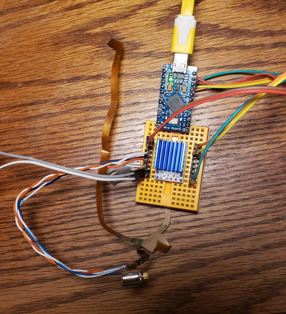
Test setup for one of these steppers

To get around the lack of documentation, I probed one out with a DMM then built a test rig out of a dual L9110S H-Bridge board and a little STM32F103 dev board with the AccelStepper Arduino library to figure out the details.

They appear to be 20 steps per revolution motors, though they seem to work noticeably better with a half-step drive pattern.
They work nicely at 3.3V, but get a little hotter than I’m comfortable with if energized for an extended period of time; I also tried 5V and it seems to tolerate that fine as well, gain a noticeable amount of extra torque, and get appreciably louder.

I don’t have the tools around to easily test the effective torque, but was way more than I expected based on my experiences with other small hobby motors. In my little taped-to-the-table test setup (pictured), if I jammed a fingernail into the rotor when it was already at speed at around at about 1000 steps/s on a 5V supply, the motor and/or nail deflected rather than missing steps.

Motor Diagram

If you look at the motor with the output shaft facing away from you and label the four pads A,B,C,D, the phases are A-D and B-C with about 9Ω across each phase.

FPC Connector Pinout

If you look at the attached flat flex cable with the end pointed toward you, it has 7 contacts. For reference, let’s refer to them numbered 1-7 left to right. The ribbon itself is 4mm wide, and the contacts appear to be 0.5mm pitch, so it would probably mate with any of the various “7Pin 0.5mm Pitch FFC FPC” connectors floating around on the market for cheap if you wanted to spin a driver board for it that used the included cable.

The last 4 cable pins correspond to the motor terminals 4-D, 5-C, 6-B, 7-A… but for experimentation it’s easier to just solder leads directly to the motor pads. I used two pairs out of some old stranded CAT5, visible in the top picture.

IR Reflective Object Sensor Breakout


There is a bonus component on a little arc-shaped boardlet built into the flat flex. It appears to be some manner of reflective infrared optical sensor, which I assume was used to establish a home position in whatever these were designed for use in – frankly since it has convenient mounting holes and wiring it would be pretty nice to use the same way in most applications I would want one of these in.

The first three ribbon pins are attached to this part, and none of these pins are shared with the motor itself. For discussion, let’s number the pins 1,2 left to right on the side toward the flex cable, and 3,4 right to left along the other in typical IC fashion. The pins are broken out Part 1 = Flex 1, Part 2 = Flex 2, Part 3 = also Flex 1, Part 4 = Flex 3.

Two of the pins (+ on 2, – on 3) appear to be a diode with a 1V forward voltage, and after I thought about it and checked with a camera with a bad IR filter, it is an infrared LED. The other pair seem to be a phototransistor or similar; it reads about 1.5MΩ from pin 4 to pin 1 in darkness and 1KΩ across the same with an IR LED pointed at it.

I’m not sure what I’m going to do with these, but they seem promising for small motion systems, especially since (if I bought bulk packs of each from China) you could get the motor and pair of H-bridges to drive it for under a dollar. Hopefully I’ll run into something to play with them in and/or my reversing work will enable someone else’s cool project.

Posted in DIY, Electronics, General | 2 Comments

Some Cheap 3D Printer Upgrades

Photo of Anycubic Kossel on top of a concrete paver + upholstery foam isolation platform.
Paver + Foam isolation Platform

I’ve had an Anycubic Linear Kossel for several years now, and have generally been quite pleased with it – if Anycubic were still selling them I’d still be suggesting them as ideal first printers.

It has produced quite a number of useful pieces, a decent assortment of household conveniences, and the usual selection of toys and meme trash for myself and others.

I’ve made a couple recent upgrades that seemed worth documenting.

Continue reading
Posted in DIY, Electronics, General, Objects | Leave a comment

Floppinux Fixed for i486 and Up

I got nerdsniped bad.

floppinux, a one-floppy busybox filled initrd based Linux “distribution” that Krzysztof Krystian Jankowski made from modern parts did the rounds the other day, and I was excited to try it on real old hardware.

Yesterday I pulled my ThinkPad 560E out, dd’d a floppinux on to a real floppy, booted it up and… it traps on an invalid opcode as soon as it tries to load init.

A little thinking made me realize that the way they were building their busybox binary was contaminating it with libraries from the system they were building on (which was apparently i686), so despite all their “will work on a 486 or later” option selections, the images they produced only work on i686 or later boxes.

I opened an issue then got obsessed and decided to fix it myself, and … you can read the details in my followup to the issue.

The magic lazy out for this kind of thing now is the pre-built musl based cross toolchains provided by https://musl.cc/

I made a couple other suggestions (about using musl, about configuring the kernel for xz and using it for the initrd, etc.) while I was hacking, because putting together little cross-compiled Linuxes is something I used to know what I was doing with. It did take a couple hours to spin back up, there are always picky cross-environment things to remember, and things have changed, mostly for the easier.

I’ve posted a copy of my generated i486-clean image. (Subsequently swapped out for a rebuild with slightly more useful busybox and kernel options, but only about 450k free)

Posted in Computers, DIY, General | Leave a comment

Not that I’m a frequent IRC user for the last several years, but since the freenode implosion seems to have settled out as a real thing, I’ve gone ahead and registered myself as pappp on oftc and libera.chat where the various projects I occasionally pop in on have moved.

It’s a shame the long-stable single place for all the open-source project channels has gone away, but at least IRC is an open protocol so we can all just move to different servers when shit goes down.

Posted on by pappp | Leave a comment

Over-Designed Model Paint Shaker

An over-designed and useless agitator for Testors enamel bottles

…An otherwise useless exercise in rapid prototyping.

Continue reading
Posted in DIY, Electronics, General, Objects | Leave a comment

Toys for my Escape Velocity Itch

Printed and painted Kestrel and Lightning models on a PowerBook 5,4

I had my regularly-scheduled itch to play Escape Velocity or one of its successors and/or clones the other week, and decided to play the real thing this time since I did a lap on Endless Sky not too long ago, and NAEV still doesn’t quite grab me.

I’m now most of the way through a game of EV (under emulation in Basilisk II), and …impulse bought a cheap 2004 15″ Aluminum PowerBook G4 (a 5,4) off the internet after a crash ate a save file. I have good coverage of Apple 1984-1994 in my collection (in the form of bulky desktops with CRTs), and x86 OS X is pretty easy to run in a VM, but I have a hole in the late PPC era. That machine will hopefully eventually also get its own post as I finish fixing it up, it’s not in perfect condition but it auctioned below prevailing when I was looking, and seems to be acceptable.

While I was looking into the player communities (…because it’s become very hard to set up a working install of EV Nova recently, and I can’t find a backup of my registered copy) I discovered that a couple months ago some wonderful person (slurked on thingiverse/quarmus on reddit) made and shared 3D models of the Kestrel and Lightning ships from the original EV.

…So the little Mac-user child of the 90s in me promptly headed down to the basement to print a Kestrel and a pair of Lightnings.

I gave them a quick sand to take the worst print artifacts off and sprayed them down with a couple coats of gray Krylon Fusion, which gave a decent base coat. I needed to do a little (bad) detail painting on the Lightnings, and the acrylics I have around didn’t stick well to the spraypaint, so I dug out my decades-old Testor model enamel set. Eventually they were shaken and stirred enough to get the job done; in another post post, an absurd over-engineered shaker that didn’t really solve the problem.

EV is still one of my favorite games, though I think Endless Sky’s implementation of the formula is actually significantly better for a modern player without the memories, especially now that Ambrosia is defunct and the hacks around registering Nova seem to not be working.

Posted in Computers, DIY, Entertainment, General, Objects | Leave a comment

Resistor Storage

As I continue my electronics part organization spree, I was looking for …something… reasonable for through-hole resistor storage. Resistors are a problem because there are a lot of values, once mixed they’re possible-but-irritating to distinguish, and strips of resistors are awkwardly shaped.

There are some special-purpose drawers, most of which aren’t very flexible (configured to hold exactly the E12 series, or with slots too small for the 4″ strips a lot of cheap resistors come in, or…), and many of which are enormous 3D printing projects in their own right that I didn’t feel like dealing with. There are some systems with small or card-catalog style drawers, but I don’t stock large enough quantities of resistors to invest that kind of money/space, and don’t plan to. I also looked at variations on schemes using card holding binder pages, since I really like the cheap SMT binders (link is the ones Adafruit stocks, mine are all the ubiquitous brown ones with gold-debossed Chinese text because I’m cheap), but after I bought a pack of the appropriate business card slot binder sheets I realized I’d underestimated my size requirements.

After quite a lot of looking around and stalling, the only thing that really appealed to me was cloning Zach Poff’s Edge-Labeled Baggie Method, so I did.

I added some E24 values (like 51x and 75x) that I had stocks of from one purchase or another, and a few other odd labels that I happen to have stocks of. The added labels are missing the cute little colored resistor images because I’m not sure how they were generated and it wasn’t urgent enough to spend a ton of time on – I just put the value and the band numbers on those.

I did cheap out on basically every part; I used 2mil 3×4″ baggies instead of the nice 6mil ones, and I used AmazonBasics 1 x 2-5/8 Inch labels that list themselves as compatible with Avery 5160 labels. Both of those may eventually prove to be a mistake, but for now they work and feel fine.

One thing I am looking to improve upon, I currently have them stored in an old Kroger deli meat tub, which is OK but not ideal. I don’t think I can find something that will hold them reliably and still clear the 3″ height of the drawers I’ve been packing a lot of my component assortments into, so I’m probably looking for something that will close, possibly a large-ish 3×5 card organizer.

Posted in DIY, Electronics, General, Objects | Leave a comment

Akro-Mils/Harbor Freight Small Drawer Dividers (in FreeCAD)

Installed polycarbonate drawer divider, next to the CNC setup it was cut on.

I’ve been doing some component stocking lately, and haven’t really set up a solid storage system, so I picked up a Harbor Freight 40+1 drawer cabinet thing to manage various small size + small quantity parts.

There are slots in the drawers to take dividers, but Harbor Freight doesn’t sell them, and Akro-Mils charges a bit much – somewhere in the vicinity of $10/16pcs – for injection molded dividers that experience says don’t fit terribly well. The set of Akro-Mils drawers I use on campus for kitting out instructional labs has first-party dividers that tend to float just enough to get pins trapped under them, which leaves me less than enthusiastic about spending money on those.

I saw some folks 3D Print their own, but always feel silly 3D printing flat parts, and wanted something clear.

..So I took some measurements, ordered some 0.078″/2mm polycarbonate sheet, and CAD’d up the shape.

FreeCAD render of tool-path, with process tree visible.

I did a quick parametric sketch/extrude/profile in FreeCAD 0.18, and unlike the last couple times I tried to build something in FreeCAD, the Sketch constraint system didn’t bug out, the Path workbench didn’t crash, and it posted reasonable gcode. I am very pleased by this development.

Now, it is a trivial part (rectangular, 2mm thick, 34mm tall, 50mm wide for the bottom 17mm, 51mm wide for the top 17mm), but I had earlier versions of FreeCAD fall over on similarly-trivial projects, usually in the path workbench. I’d really like to have (and be vaguely competent at using) a decent all-FOSS design flow for the router, so this is an exciting development. File here if anyone wants it.

There was the usual CNC fuckery (losing Z steps because I plunged too aggressively for the bit, tapping the Z- stop because I had the spindle raised in its clamp for working off a vise and forgot, etc.), some of which were solved by finally switching my Z axis motor to a slightly higher current since I keep having problems with running out of Z force.

Had I looked a little closer I would have noticed there are third party laser-cut acrylic dividers available for like $0.33/ea compatible with the Akro-Mils small drawer size, but if you ignore the …$1000-odd of CNC machine and tooling and the value of my time… these come out to like $0.16, so it’s not completely absurd from that angle, and it was a good tool-chain test. Also, happily, they fit significantly tighter than the Akro-Mils injection molded ones, so no trapped pins.

Posted in DIY, Electronics, General, Objects | Leave a comment

While giving a student some hints about an ARM assembly assignment I just noticed that google services (eg. gmail) want to auto-complete “R0” to “R0lGODlhAQABAIAAAP”… which, upon inspection, is the base64 encoding of a 1px transparent gif, something spammy over-formatted marketing mail is full of. Good job ML tools, good job.

Posted on by pappp | Leave a comment

4+1 Multi-pens: A Survey

My increasingly absurd 4+1 multi-pen collection, left to right:
Dr.Grip 4+1, Uni Style Fit Meister 5, Zebra Clip-On Multi, Zebra Sarasa, Hi-Tec-C Coleto 5, Uniball Jetstream 4&1

I’m a little obsessive about my everyday objects, in that stereotypical engineer “determine an optimal solution and stick to it” sort of way. For about a decade I carried a little (handmade, periodically replaced) sleeve with a Bic MatiC grip 0.7 pencil and Black, Blue, and Red Uniball Vision Elite pens in 0.5mm (plus a chapstick and flash drive).

Trusty old Pocket Organizer

That utensil set is for a note-taking system where my own work and other temporary or uncertain things are in pencil, notes and other reference material are in black, provided examples and commentary are in blue, and corrections and attention points are in red. Diagrams are multi-colored for clarity.

I have a ritualized paper-handling (I carry a clipfolio and periodically file into binders), page-labeling (Top right,Topic/Date/Sequence Number), bullet hierarchy (A little drift over the years, but mostly ⊕ > • > ⁃) , and archiving (Rarely-used topics get twist-ties through the binding holes and stored in boxes) system that I’ve been using for decades at this point.

Since 2019 I’m primarily teaching labs, so in addition to my own note-taking I do a lot of drawing examples and correcting solutions where a variety of colors is useful, and I kept wanting more than the 3+1. Carrying around a whole stack of writing utensils seemed unreasonable… until I found a 4+1 multi pen I got as conference swag, and it set me off on an expedition.

I tried my conference-swag Zebra Clip-On Multi for a few weeks, liked it for the most part but missed the writing quality of my Vision Elites, got slightly obsessed, and bought examples of most of the 4+1 pen bodies on the market to compare. Then I used each for a week during the Fall ’19 semester to get a feel for them.

TL;DR
My current favorite 4+1 multi-pen body is the Pilot Dr. Grip 4+1, loaded with Uniball Signo D1 refills and Pentel Ain Stein HB lead. It’s only major weakness is the covered tiny eraser.

Continue reading
Posted in DIY, General, Objects | Leave a comment