
I impulse bought a 5 pack of tiny stepper motors off Amazon for $3 to satisfy my curiosity. A colleague showed them to me and asked if I knew anything about them and …I didn’t, but they were too cheap and interesting not to try.
I couldn’t find any documentation on the internet from the identifying marks, so I burnt an afternoon figuring them out, and I’m posing my notes in case anyone else wants to make use of them.
Amazon product is “5 Pcs 2 Phase 4 Wire Micro Stepper Motor with Cable 3-5v Dc Dia 8mm Mini Stepper Motor Micro Stepping Motor for Digital Products Camera”. They look like they’re drop-in replacements or surplus from the production of …something… but I don’t see any obvious leads as to what.
The labeling on the motor itself is “SRG0808 003PLK5” which doesn’t turn up anything useful in a quick search, and the bag they came in is labeled “Fashion Worlds stepper motor 9496 x5” which is also not something googlable.
The motor comes attached to a flat flex cable with various adhesive pads built in, a boardlet, and a connector at one end. The output shaft is set in a brass gear roughly 2.75mm diameter with 12 involute profile teeth, about 3mm long – I don’t know small gears well enough to infer a ton from this, but it does seem like there is a lot of compatible gearing on the market.
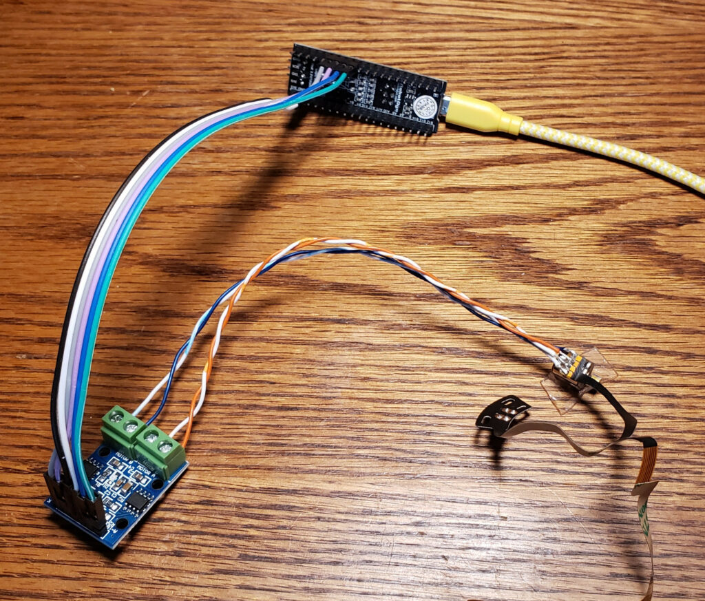
To get around the lack of documentation, I probed one out with a DMM then built a test rig out of a dual L9110S H-Bridge board and a little STM32F103 dev board with the AccelStepper Arduino library to figure out the details.
They appear to be 20 steps per revolution motors, though they seem to work noticeably better with a half-step drive pattern.
They work nicely at 3.3V, but get a little hotter than I’m comfortable with if energized for an extended period of time; I also tried 5V and it seems to tolerate that fine as well, gain a noticeable amount of extra torque, and get appreciably louder.
I don’t have the tools around to easily test the effective torque, but was way more than I expected based on my experiences with other small hobby motors. In my little taped-to-the-table test setup (pictured), if I jammed a fingernail into the rotor when it was already at speed at around at about 1000 steps/s on a 5V supply, the motor and/or nail deflected rather than missing steps.

If you look at the motor with the output shaft facing away from you and label the four pads A,B,C,D, the phases are A-D and B-C with about 9Ω across each phase.
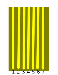
If you look at the attached flat flex cable with the end pointed toward you, it has 7 contacts. For reference, let’s refer to them numbered 1-7 left to right. The ribbon itself is 4mm wide, and the contacts appear to be 0.5mm pitch, so it would probably mate with any of the various “7Pin 0.5mm Pitch FFC FPC” connectors floating around on the market for cheap if you wanted to spin a driver board for it that used the included cable.
The last 4 cable pins correspond to the motor terminals 4-D, 5-C, 6-B, 7-A… but for experimentation it’s easier to just solder leads directly to the motor pads. I used two pairs out of some old stranded CAT5, visible in the top picture.
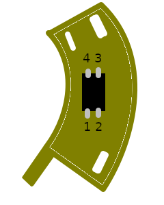
There is a bonus component on a little arc-shaped boardlet built into the flat flex. It appears to be some manner of reflective infrared optical sensor, which I assume was used to establish a home position in whatever these were designed for use in – frankly since it has convenient mounting holes and wiring it would be pretty nice to use the same way in most applications I would want one of these in.
The first three ribbon pins are attached to this part, and none of these pins are shared with the motor itself. For discussion, let’s number the pins 1,2 left to right on the side toward the flex cable, and 3,4 right to left along the other in typical IC fashion. The pins are broken out Part 1 = Flex 1, Part 2 = Flex 2, Part 3 = also Flex 1, Part 4 = Flex 3.
Two of the pins (+ on 2, – on 3) appear to be a diode with a 1V forward voltage, and after I thought about it and checked with a camera with a bad IR filter, it is an infrared LED. The other pair seem to be a phototransistor or similar; it reads about 1.5MΩ from pin 4 to pin 1 in darkness and 1KΩ across the same with an IR LED pointed at it.
I’m not sure what I’m going to do with these, but they seem promising for small motion systems, especially since (if I bought bulk packs of each from China) you could get the motor and pair of H-bridges to drive it for under a dollar. Hopefully I’ll run into something to play with them in and/or my reversing work will enable someone else’s cool project.

Thank you very much for taking the time to do this. I purchased them and asked questions to the seller but got no answer. You answer most of my questions but I still don’t know the size of the screws to mount this baby. If by any chances you do know, please share the info. Thanks.
It’s below the range I stock, it _might_ be M1-0.25 because I can just barely insert a 1mm pin into the holes, but that’s a punt.