I wanted some chamber / flood lights in my Voron Trident, and couldn’t find design I liked, so I made my own. I’m not an expert at mechanical design/CAD, and slowly getting less-bad at FreeCAD, but I’m pretty happy with the result. It’s now available on Printables.
I decided it was time for a 3D printer upgrade recently. I did some playing with my old Kossel, adding braces and changing some tuning since it runs Klipper, and while it continues to be a fine machine for small PLA parts, and a fun project, I wanted more volume, more speed, and an enclosure so I can run a wider range of materials. Instead of doing something reasonable and spending O($500) on one of the various commercial options that meets the “Enclosed, Larger, Faster 3D printer that I can run a wider range of materials on” prompt (the Qidi Q2 was a close contender) I decided I wanted to build a Voron Trident.
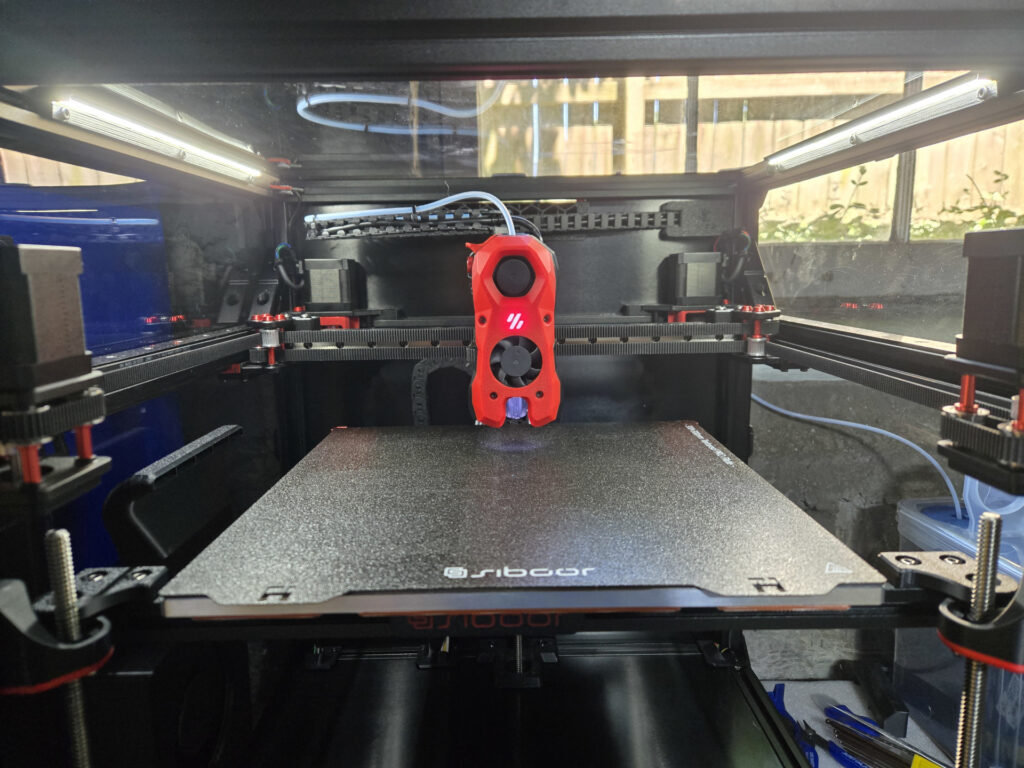
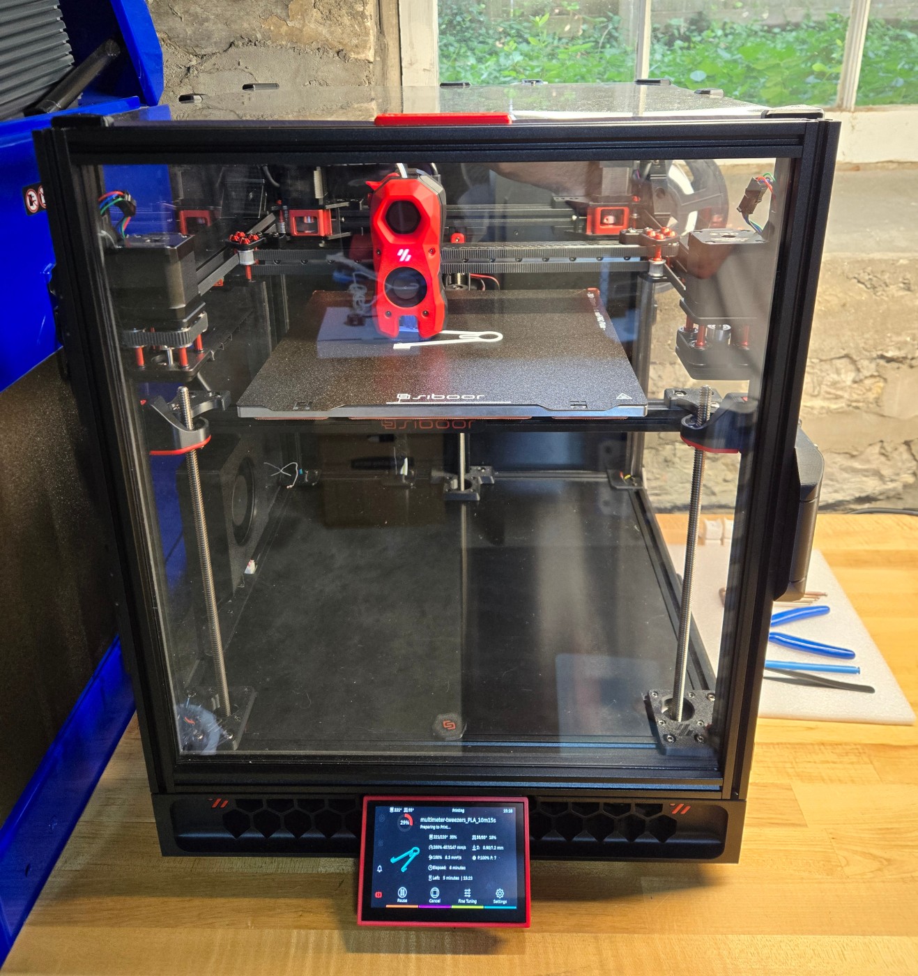
I did “some” reading so I had opinions on mods I wanted out of the gate… and ended up buying one of the ‘roided out Siboor Voron Trident “June ’24” 300mm CNC/AWD kits for (once import duties were paid and such) about $1500. That includes their “Booster Pack 1” option, so it has steel backers on Y, aluminum gantry corner braces (this was the feature I cared about – triangles are good), and TMC5160Ts on the X/Y motors, in addition to the kit standard CNC gantry with double-shear mounts and AWD (they nicely include the 2WD idlers as well, but don’t document the belt path using them), 9mm belts, inverted electronics, clickyclack door, fume pack, and (frankly kind of questionable) side booster fan. I thought I was getting a CB2 for the computer, but it came with a Pi CM4 (CM4102032), which I’m pleased about. I went for Siboor’s kit despite the Trident R2 already being partially announced because I wanted several of the nonstandard features they bundle, and I wanted to be sure I had it while I had time to spend the several-tens-of-hours to build and tune it before I had academic year obligations.
I ordered the kit via Siboor’s Aliexpress storefront May 14, it was delivered June 10, and printing June 20. It’s currently built essentially to kit instructions, and I’m very pleased with the build process and result. Since so much knowledge about these things is disappearing into search-proof proprietary silos (lookin’ at you, Discord), too much detail below.
TL;DR: If you have one of those sketchy Chinese metal-cage 500W spindle speed controllers that uses a potentiometer for speed control, the potentiometer terminal block is probably referenced to a dangerous voltage, be careful what you connect to it and/or replace it with a less dangerous one.
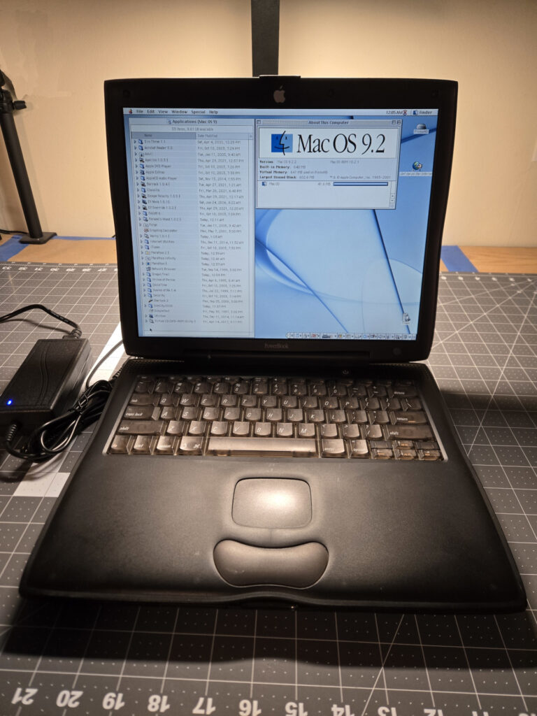
I’ve wanted one of the curvy bronze-keyboard G3 Powerbooks since they were new – I’ve always been kind of taken by the design language (half business, half iBook). I got to play with a university-owned Wallstreet for a while as a kid, so I remember them beyond looking in catalogs, and uh… I really like a bunch of classic Mac games and want a convenient late-classic machine to run them natively, because a few are glitchy in emulation.
So, I occasionally lowball bid promising auctions when one comes up somewhere. A few months ago (in late February) there were a succession of them on ShopGoodwill, and I tossed a $50 max bid on a Pismo in the 500MHz/128MB/12GB/DVD configuration in unknown electrical and OK but not perfect cosmetic condition. And, surprisingly, won. It ended up being about $67 with shipping/handling/tax/etc. Since working condition examples tend to be around $200, this seems like a decent deal. It survived the typically awful shipping, and, in long form below, it turned out to be a good buy.
I’ve had a few projects recently that needed 3D printed parts, went to use a roll of black eSun PLA+ that I accidentally left out in my basement for some time, and it produced the telltale dull, rough, stringy, gappy print quality of hydrated filament. Since I have some energy for projects right now, I decided it was finally time to get a filament dehydrator setup.
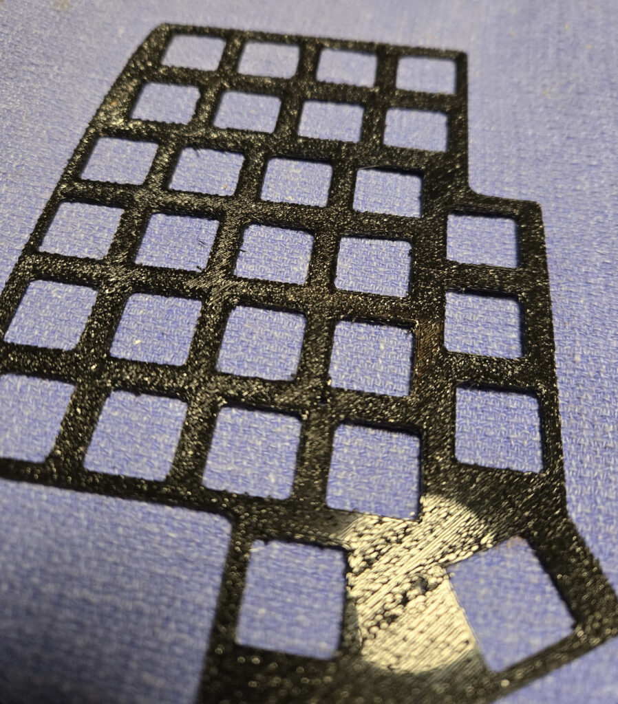
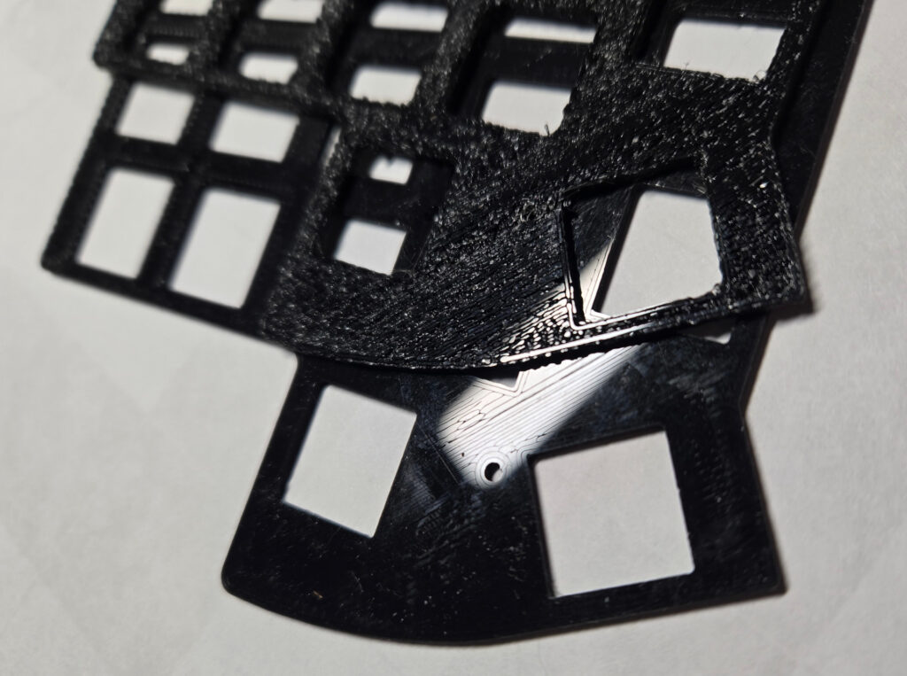
Pretty sure PLA printed to a glass bed shouldn’t look like this…
I went reading up about filament dehydration. The purpose-made filament dryers mostly seem to have a problem with actually removing moisture, most of them are dry boxes with no exhaust path, and the liberated water vapor has to go somewhere. Many seem to rely on instructions for the user to periodically open the lid during drying (which is …not automated), and a few contain a large amount of desiccant that will be more-hydrophilic than most filaments at drying temperatures, then itself require dehydration. Bambu seems to be doing basically the right thing with the AMS2 Pro and it’s automatic exhaust valve, but I’m not in the Bambu ecosystem and not looking to spend that kind of money.
So, instead, I looked at the DIY options. There are a variety of clever schemes with PID controllers and heating elements… but lot of folks seem to just repurpose inexpensive food dehydrators, and I went with a variation on that plan.
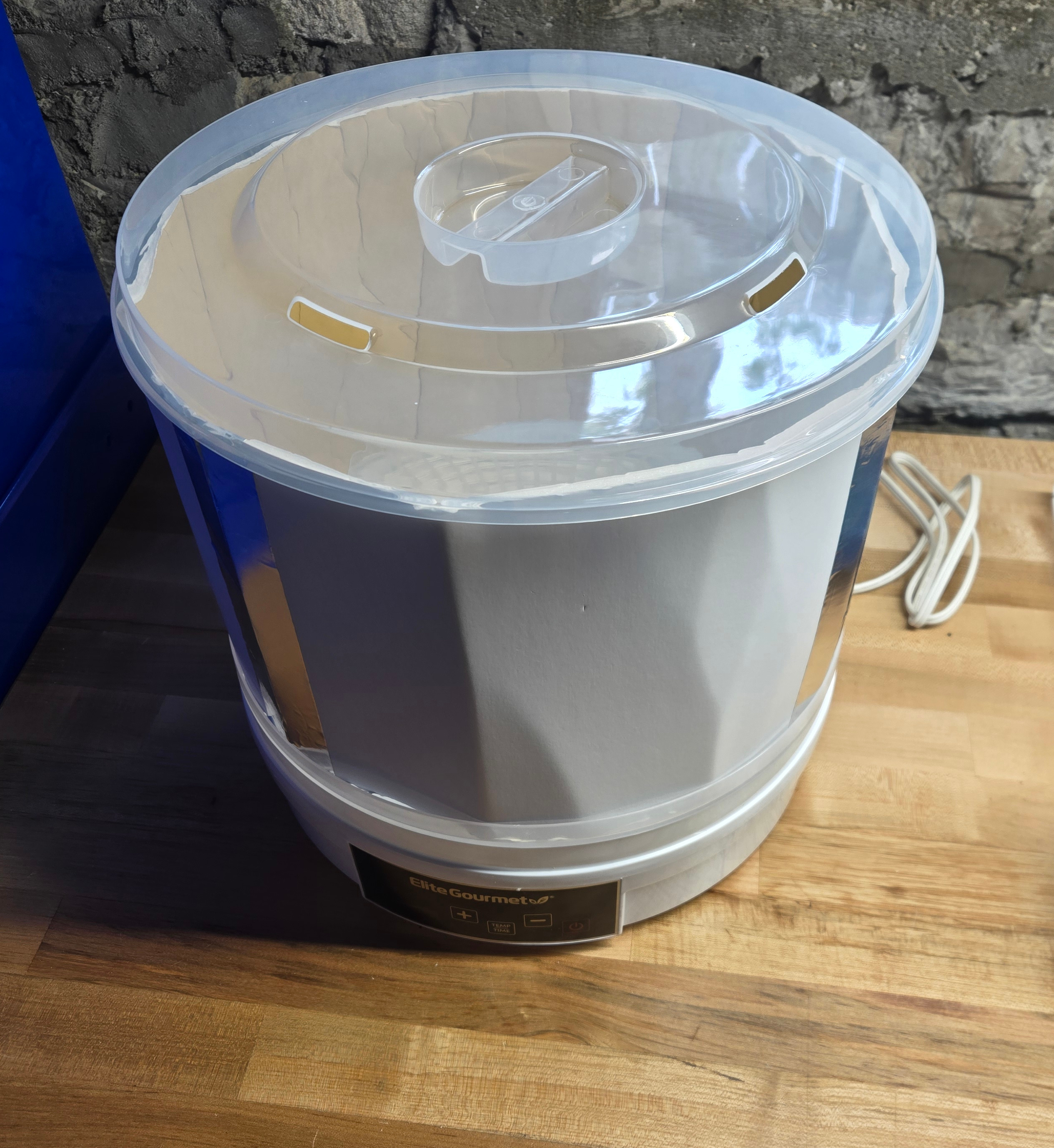
I picked up a $40 Elite Gourmet EFD770WD dehydrator; I paid a few extra bucks for a model with a digital thermostat/timer. It gets me a heater, a blower, and thermostatic control in a package that is at least theoretically safe for consumer use, which is really all that is called for. There are many directions on the internet for cutting the grilles out of several trays on this style of dehydrator to make a spool-sized cavity, and many designs for large, elaborate, and almost inevitably multi-part printable extension tubes, which must be printed in a filament still rigid at the highest drying temperature you expect to need. The former seems wasteful and the latter seems like a tedious hassle.
A little foamcore and tape to make a suitable cavity.
I did something much lazier and made a tube out of foamcore. Just bent it using the little tabs for aligning the trays and taped. Mine is two pieces because none of my scrap pieces were quite large enough to do it in one. The foamcore is slightly insulating which seems like a minor feature, and this method isn’t many hours of printing or destructive, which is a major feature. I also saw several folks modifying a 3.5gal or 5gal paint bucket with a diameter around 12.5″, and I may try that in the future as a more polished solution, but didn’t have a suitable empty on hand.
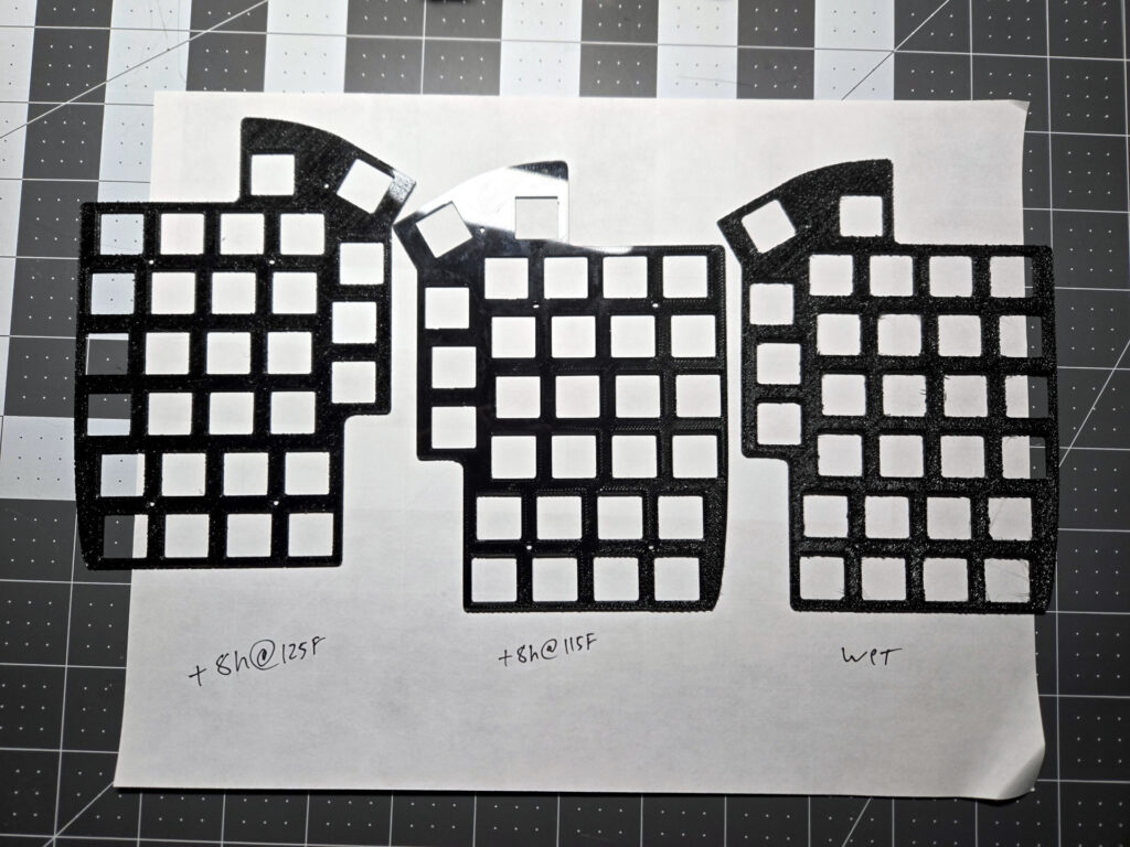
This particular dehydrator only lets you pick specific temperatures, but 115 and 125F are options right to either end of the suggested range for drying PLA variants. As for effectiveness, the main subject roll of black eSun PLA+ that sat out for a couple months, whose behavior is pictured above, went in for 8 hours at 115F, and initial results were really promising.
The first experiment looked really promising; Same printer, same gcode, top print before drying, bottom print after 8H@115F. Almost all defects were gone from the first layer.
There were still some hydration-looking defects in areas (and the thermocouple I had shoved in through one of the lid slots of the dehydrator as a safety was reading a little low), so I gave it another 8 hours at 125F. And the results didn’t really change, but there was no obvious degradation. It has a dead spool producing parts that are usable if a little textured, which is worthwhile.
Similar parts printed wet, dried for 8 hours at 115F, and dried an additional 8 hours at 125F. It’s unclear if the subsequent/hotter drying offers any significant benefit.
PLA+ is always a bit of a mystery material, I’ve generally supposed that much of it is doped with a couple percent PBT, but the relevant eSun PLA+ MSDS just shows 2-4% calcium carbonate (which apparently just provides nucleation sites to improve the crystallization) and 2-5% “other,” (likely pigment). CaCO3 isn’t very soluble in water, but who knows how it moved around or altered crystallization or whatnot during the wet-dry cycle. I ran some Inland “Egyptian Blue” regular PLA that had sat out in the basement for a while through a similar 8h@125F cycle and it did seem to reduce the surface irregularities (pips, especially on corners) between the previous and next part I printed in it, but not in such a dramatic way.
From a somewhat-amateur reading of the relevant literature, it seems like not all the hydration induced changes should be reversible. The most relevant thing I could find was Beyond Biodegradability of Poly(lactic acid): Physical and Chemical Stability in Humid Environments (2017) which looks at degradation due to liquid and vapor phase water infiltration, and found pretty substantial chemical changes especially from vapor at higher temperature. The literature in general is a little spotty, there are more liquid phase studies (eg. ref), but studies like the earlier one comparing liquid and vapor phase water infiltration indicate they aren’t entirely comparable. The literature on drying is “thin,” and the relevant Internet content is thoroughly astroturfed by vendors trying to sell you gadgets (which is becoming a real problem in the 3D printing market in general; good luck finding un-sponsored information about anything). I’m sure some of the commercial (bio)plastic manufacturers/processors have detailed internal documentation, but they aren’t sharing.
In the same order as they dryer, I picked up some indicating desiccant packs to improve my ability to monitor and dry filament in bags. I’m so distrustful of Amazon junk now, I stuck one in the bathroom to absorb shower steam to see what the indicator hydration process looked like, and it is slowly turning pink after being repeatedly exposed to shower steam. Hopefully storing filament with known-dry desiccant will help keep it from going bad – at least as long as I continue avoiding any of the truly hydrophilic materials like Nylon that require special handling.
All in all: Hydration is absolutely a problem for PLA and adjacent materials, drying is imperfect but effective, slightly modified food dehydrators that exhaust the vapor do a fine job, and keeping material dry is better than trying to dry it.
TL;DR: I converted my Anycubic Linear Kossel to Klipper. Using a hacked Chromebook as the host, which is great and I recommend hacking surplus education market Chromebooks for many of hobby projects usually done with an SBC. Running in containers as a docker-compose project, which works but is dumb and wasteful. Next I’m going to try to do some systematic performance experiments to it, but that’s for a later post. Details below.
Between having more disposable income and the potential for upcoming trade weirdness, I’ve been pretty fast-and-loose about buying random bullshit that catches my fancy from China of late.
A recent Aliexpress order consists mostly of USB tampering supplies, like an exhaustive set of breakouts for all the common USB connectors, including a couple extra type C breakout boards because I’ve been doing a bit of Chromebook abuse recently and a SuzyQ cable is likely to come in handy.
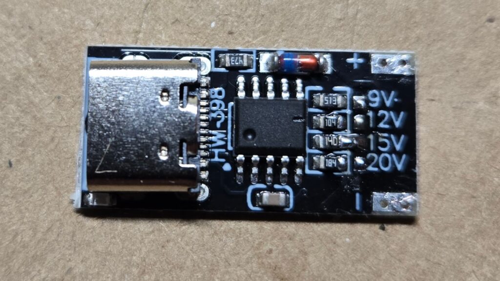
In that batch, I also picked up a 10 pack of these little HW-398 USB C PD trigger boards (aka Decoy boards). They have a USB C Female connector on one end, + and – pads on the other, and a series of little pads marked with voltages that you can solder bridge to an adjacent resistor to have it negotiate that mode – apparently via any of the PD/QC/AFC protocols for doing so. They seem like they should be useful for powering projects from easily obtained junk, but merit investigation because they also seem a little sketchy and were a whopping $0.63/each.
A couple of the behaviors and design decisions are interesting:
The USB C connector is slightly inset on the PCB, which is probably good for strength, but rather unfortunate for mounting it into a project.
They DO supply 5V when none of the higher values are selected, which is both reasonable and desirable.
There is a little blue indicator LED next to the plug, and it’s marginal at lower voltage.
It appears if you set a voltage not supported by a supply, you get the next voltage down, which I gather is suggested by the standard. This is not unreasonable but has real potential for unwelcome surprises if you don’t protect your design. The most likely issue seems to be a lot of supplies don’t support the optional 12V mode: I didn’t thoroughly test, but I popped one strapped for 12V onto a little Anker 313 whose label says 5V@3A,9V@3A,15V@2A,20V@1.5A and it delivered 9V.
The IC is conspicuously unlabeled. It’s an SOP10 package, and is smart enough to do to necessary USB negotiations (which are actual USB protocol traffic performing a handshake to read and write some control registers at either end). A little googling seems to imply the chip is a Fastsoc FS312 – It’s in the right package, supports PD,PPS, and QC negotiations, which lines up with the product description, and the setting straps are connecting resistors of values 184(180kΩ)=20V, 140(14Ω)=15V, 104(100kΩ)=12V, 513(51kΩ)=9V which matches the datasheet.
I haven’t done any load testing, but I don’t see any sign of regulation on the board, so I suspect the regulation will depend entirely on the supply.
I have no idea if the USB IF considers these legitimate.
It certainly seems like a useful gadget for the parts bin. LCSC doesn’t seem to stock the FS312 IC, which is a shame since now that I know they seem to just work with the very minimal suggested circuit in the datasheet that requires only a capacitor and resistor beyond the chip and connector, I’d start designing them into boards if I could get them stuffed by the usual scumbags.
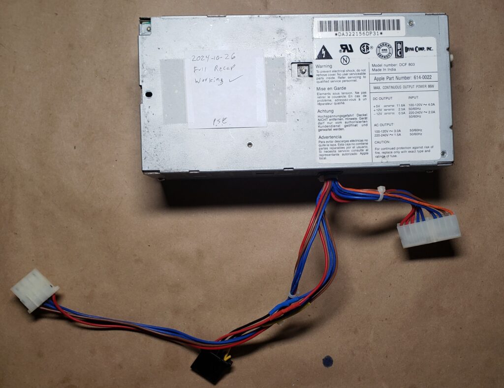
Since finally being rid of my PhD work, I’ve been hitting a bunch of projects that have been on my TODO list for ages. The oldest so far is this PSU which has been sitting for …decades… in my parts pile with some compatible machines, and I’ve always intended to try rebuilding it. It died with a “ticking” symptom some time in the mid-00s.
I finally got around to it this week, and it wasn’t a bad job. About $10 of parts, a few hours of work, and it’s back in action. Rebuild details below.
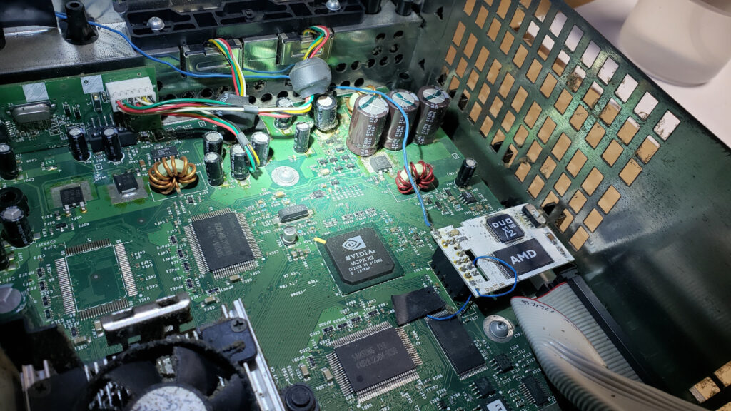
If you have an OG Xbox sitting on a shelf somewhere, this is your reminder to pull the clock capacitor and clean up whatever corrosive goo it has already vomited out. I was talking old video games with a student in one of my labs this week and it reminded me that this is one of the many projects I’ve been meaning to get to but haven’t had time for for the last several years.
Microsoft used some cheap 2.5V 1F early super caps which will inevitably fail and spray electrolyte on your motherboard, because they made some cost-cutting choices about the RTC, so now everyone with an old Xbox has to fix it.
Input conditioning is one of those things that snares novice designers, causes late-process changes that overrun expectations on cost and board area, and traditionally isn’t terribly well taught to EE/CPE students.
It’s on my mind because next week is the point in the semester where I drag UK’s current crop of EE/CPE sophomores through a lab exercise I designed about 5 years ago to drive home gate delays, static hazards, switch bounce, etc.
While I was thinking about it, an upperclassman who regularly digs up neat stuff sent me the cleverest input conditioning circuit I’ve ever encountered.
The circuit comes from the late, great Don Lancaster of TV Typewriter fame, who in addition to his published designs, wrote and self-published a number of instructional/reference books. He had a well-deserved reputation for clever, cheap, robust circuit designs, and this particular trick is the highest wizardry.
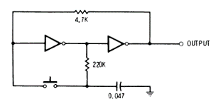
Here’s the whole circuit diagram from the text:
The design comes from his CMOS Cookbook (PDF, link to his own hosted copy of the 2nd ED), on p.317 amid a discussion of Flip-Flops and Clocks. It is presented as “An Alternate-Action Push Button” which is entirely correct but really undersells how clever it is, and has apparently been in there since the 1st edition in 1977.
The fundamental trick is that it’s a master-slave Flip-Flop where the capacitor is the master storage element, and the pair of feedback-coupled inverters is the slave. The cap tanks the next state based on the output of the first inverter when the switch is open, and induces it on the inverters on switch close. This means, in addition to latching/toggling, it de-bounces, because the capacitor sets the time constant for hysteresis. It conditions, because the load sees the output of the second inverter. No race conditions or potential oscillations, because the cap can’t charge/discharge while the switch is held. No charge is moving inside the mechanism at steady state, so it’s not leaking power. It’s brilliant.
It is only suitable for relatively slow human-scale edges, so probably not a good method for encoders or the like. You can manipulate the time constant for the de-bounce by changing the value of the capacitor, but only down to a few 10s of nF (depending on what kind of inverter you use) before it gets marginal because it doesn’t have the charge to reliably throw the input of the first inverter.
Not only is it ridiculously cheap and simple as presented, which I think intends a 4067 or 74HC04, you can built it out of anything. Any inverting CMOS gate will work. Any inverting TTL gate will work. Ridiculous old RTL or DTL inverters work. A pair of N-Channel FETs (another CircuitJS link, has an extra transistor on the output for integrity reasons) with pullups to build your own cruddy NMOS inverters works. As would P-channels with pull-downs, or BJTs with resistors for constructed RTL (though doing it that way is leaky), or various other assemblages of tiny mass produced minimum cost components to make it even more minimal (though maybe not cheaper in a modern context).
I appreciate a clever domain-crossing design, and this is the highest form.