I decided it was time for a 3D printer upgrade recently. I did some playing with my old Kossel, adding braces and changing some tuning since it runs Klipper, and while it continues to be a fine machine for small PLA parts, and a fun project, I wanted more volume, more speed, and an enclosure so I can run a wider range of materials.
Instead of doing something reasonable and spending O($500) on one of the various commercial options that meets the “Enclosed, Larger, Faster 3D printer that I can run a wider range of materials on” prompt (the Qidi Q2 was a close contender) I decided I wanted to build a Voron Trident.
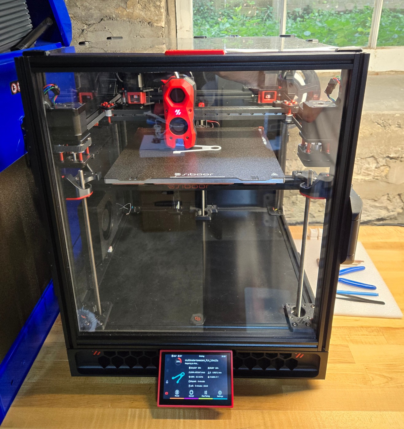
I did “some” reading so I had opinions on mods I wanted out of the gate… and ended up buying one of the ‘roided out Siboor Voron Trident “June ’24” 300mm CNC/AWD kits for (once import duties were paid and such) about $1500. That includes their “Booster Pack 1” option, so it has steel backers on Y, aluminum gantry corner braces (this was the feature I cared about – triangles are good), and TMC5160Ts on the X/Y motors, in addition to the kit standard CNC gantry with double-shear mounts and AWD (they nicely include the 2WD idlers as well, but don’t document the belt path using them), 9mm belts, inverted electronics, clickyclack door, fume pack, and (frankly kind of questionable) side booster fan. I thought I was getting a CB2 for the computer, but it came with a Pi CM4 (CM4102032), which I’m pleased about.
I went for Siboor’s kit despite the Trident R2 already being partially announced because I wanted several of the nonstandard features they bundle, and I wanted to be sure I had it while I had time to spend the several-tens-of-hours to build and tune it before I had academic year obligations.
I ordered the kit via Siboor’s Aliexpress storefront May 14, it was delivered June 10, and printing June 20. It’s currently built essentially to kit instructions, and I’m very pleased with the build process and result. Since so much knowledge about these things is disappearing into search-proof proprietary silos (lookin’ at you, Discord), too much detail below.
Continue reading