Last summer I posted about some tiny stepper motors from the internet, thinking about them as an alternative to mechatronic standbys like those terrible SG90 type servos or larger and differently terrible 28BYJ-48 geared steppers driven through a ULN2003.
At the time, I tried one with an A4988 stepstick from the top of my parts bin, and it didn’t work, so I figured there was some limitation and stuck to directly driving with H-bridges. …it turns out the “limitation” was that the cheap current-setting potentiometer on that particular stepstick was broken so it was driving no output current.
Discoveries:
Those little bipolar stepper motors work fine with bipolar stepper drivers.
Generational gains in bipolar stepper driver ICs are substantial (eg. A4988 -> TMC2208).
The venerable 28BYJ-48 unipolar stepper motor is easily modified to run from bipolar drivers.
I have an Onn Surf 8 (One of the surprisingly-not-that-shitty ultra-cheap Walmart tablets) that my research group bought a couple of to use as Android dev testbeds. I’ve been occasionally using it as a normal tablet since I have it around, and have been consistently irritated by the collection of bloatware it comes with…. so I decided to hack it. To tl;dr this whole thing, ignore the collection of typically scammy Android dev forum and blogspam crud, and use the open-source mtkclient for your MediaTek Android device hackin’ needs.
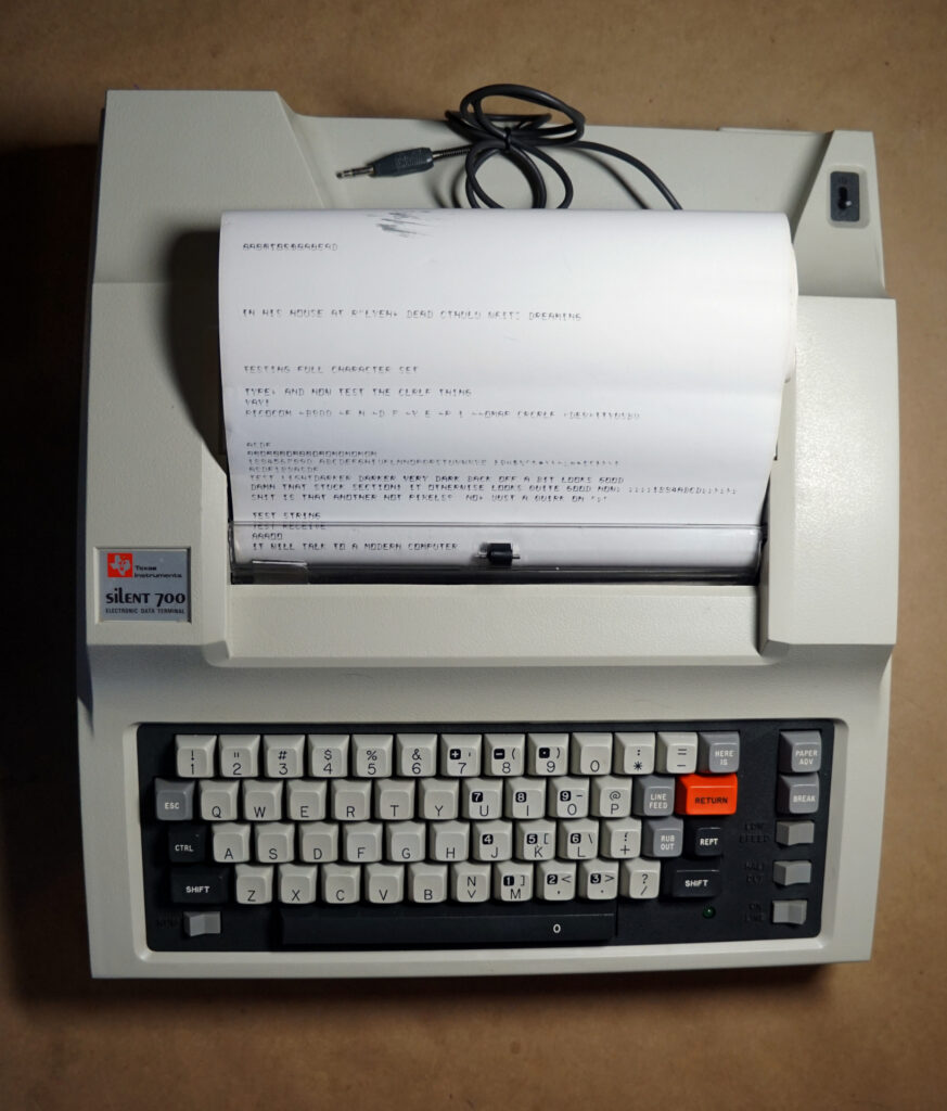
I’ve wanted a hard-copy terminal for a while – both to play with and to use for explaining why serial works the way it does, but they tend to be expensive. Most of the common hard-copy terminals also aren’t really convenient objects to own: loud desk-sized machines (Teletype 33 family, most DECWriters), additionally clockwork nightmares (IBM 2741, earlier Teletype devices), which speak ridiculous protocols (…ditto). This only leaves a handful of reasonable options, the most common of which are portables like TI Silent 700s and DEC LA12s, or one of the dasiywheel-printer based terminals (which are often non-period-correct things like a WheelWriter with a modern serial interface card in it).
So, of course, I’ve been idly keeping an eye out for a deal on one on the auction sites, and mid-October last year I got lucky: I scored a TI Silent 700 Mod. 745 for $34.00+S&H (about $47 all in) from a Shopgoodwill auction, and got it working.
An old friend of mine was moving cross-country and got in touch about taking “Some of his old computers” a while ago. I of course agreed, and it turned out to be quite a growth event for my hoard. There will be several posts about machines that arrived in this process as I get to them.
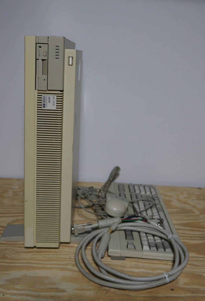
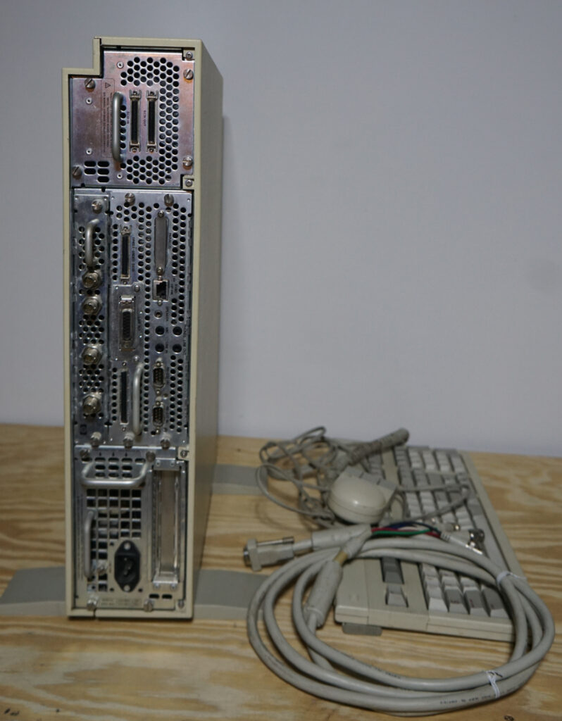
The list of things to be re-homed included “an Apollo” which I was hoping was a pre-acquision DN-something or a HP 300/400 series because I’ve had a long fascination with Domain/OS. What showed up is… not that. This is a later HP Apollo 9000/735 PA-RISC workstation, ca. 1992, which is easily the most exotic piece of hardware that transaction made me steward of. The OS options are HP-UX 7-10.20, a few BSDs, or a second-class NextStep 3.3 port; I’ll probably go with HP-UX10.2. It came with the requisite HP-HIL keyboard and mouse (thank goodness) and a DEC branded 5xBNC to VGA cable.
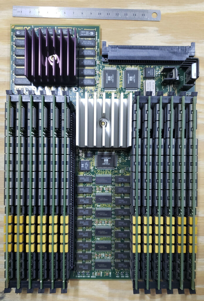
Processor board with 12x16MB Memory modules
This thing was serious rarefied-air hardware when it was new: PA-7100 99 MHz processor, 208 MB of RAM in 12 obscene proprietary 16MB RAM modules + 16 soldered to the processor board, a HP CRX-24Z video board, a full-height SCSI HDD, and an AUI Ethernet daughter card. Probably in the ballpark of $60,000 new. It is also built like a piece of high-end industrial equipment, with big sheet-metal frames with handles that pull out of the back of the system for every major component.
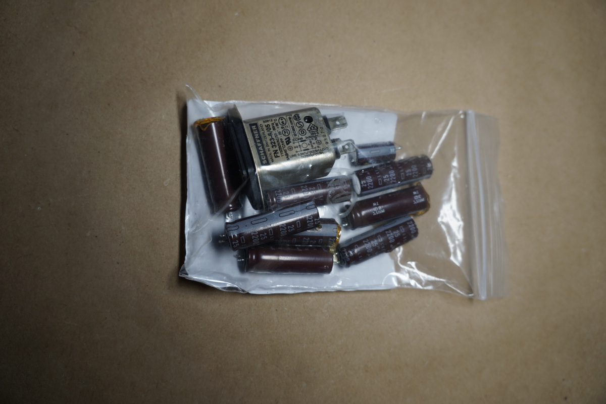
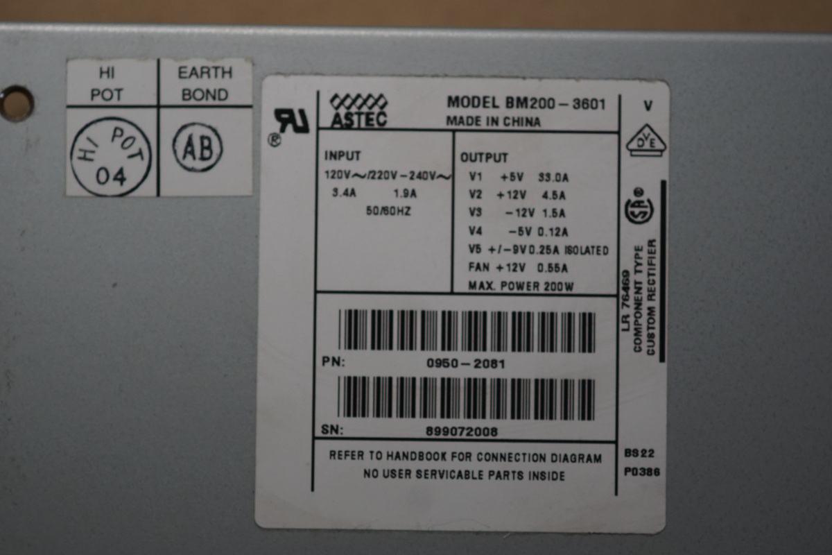
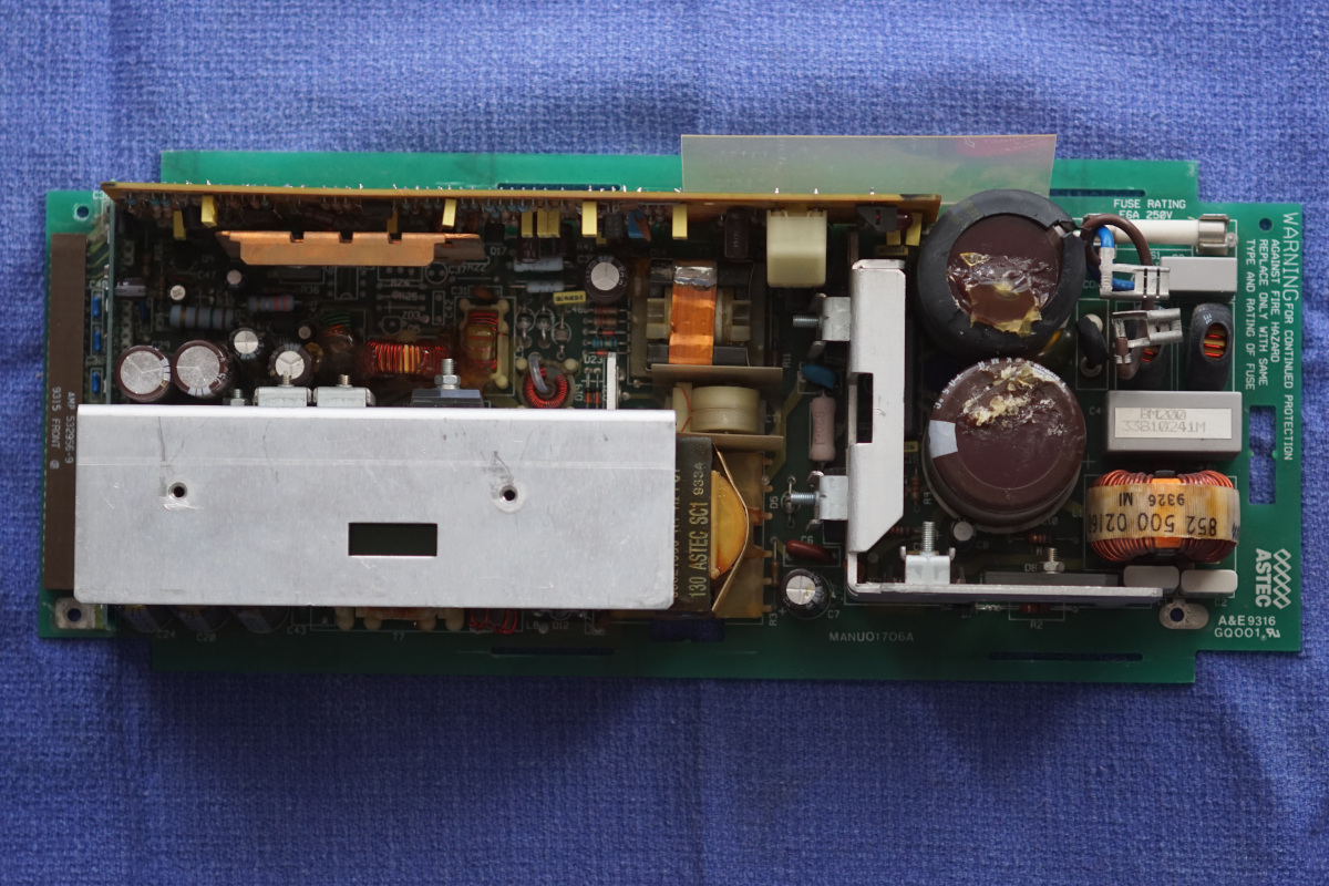
My first attempt to power it resulted in …a feeble blink of the power light. That suggested to me that the PSU was bad, probably due to defunct electrolytic capacitors. So, in standard “old electronics troubleshooting” fashion, I pulled the PSU, tore it down, read labels off the most suspicious capacitors, and ordered replacements. The HP Museum folk also suggest the AC line filter module is a time bomb on all of these, so since it’s still made, I grabbed one of those too.
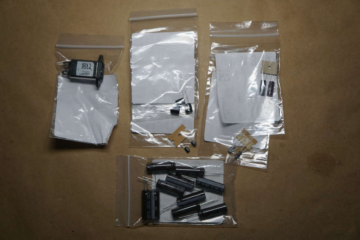
List with Mouser links, since they were the vendor with everything I needed in-stock: 8x 2200uF 25V, 12.5mmD 40mmH, 5mm lead spacing , Nichicon UPJ1E222MHD 8@1.09 1x 220uF 35v, 10mmD, 20mmH, 7mm lead spacing, Nichicon UPM1V221MPD1TA 1@$0.72 1x 1x 22uF, 25V, 5mmD, 12mmH: Nichicon UPS1E220MDD1TA 1@0.30 1x 12uF, 35v, 5mmD, 10mmH, Panasonic EEA-FC1V120B 1@$0.39 1x AC Power Entry Module, Schaffner FN9222R-10-06, 1@$6.50 I also ordered a couple 470uF 25V, 10mmD, 20mmH, 5mm lead spacing caps, but ended up not installing them because there was no sign of damage and they were hard to get a good angle on.
I passed on dealing with a couple smaller electrolytics with no signs of damage, and also two gigantic 2x 1200uF, 250v, 35mmD, 47mmH, 10mm lead spacing input caps that cost $7.50 a piece, since they looked both fine and like a fight to get out without damaging the PCB. One of these days I really need to invest in a proper pump-driven desoldering gun to make this kind of task safer and easier.
I of course picked up an extra 1-2 of each since it was noise over paying for shipping, and it’s a good thing because I dropped one of the new 220uF/35V parts and it instantly disappeared forever, presumably to wherever my cat has been hiding toys recently. The new input filter is slightly longer than the original and required a bit of creative terminal bending to fit around the caps, but it made it back into the case. After the recap, it powered right up, and on a second try after giving the hard disc a gentle thump to unstick the heads from park, everything spun right up.
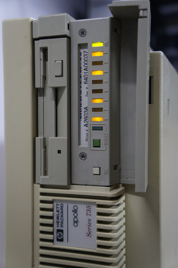
Full Status LEDs. 8,6,3,1 = “Autoselection Failure to Find Boot Device”
It booted to status LEDs at that point, and shows “8,6,3,1” which according to the service manual indicates “Autoselection Failure to Find Boot Device” – probably meaning the HDD is dead and/or wiped. The appropriate HP/UX media is easy enough to find. Unfortunately, the monitor on my basement bench doesn’t seem to want to sync with the presumed 1280×1024@72Hz Sync-on-Green coming out of the video card, so I’m stuck for now until I can find a workaround. There is a 4th BNC labeled “Stereo” that might somehow be useful for sync? Or I need a scan converter/sync stripper gadget? … further research required.
I impulse bought a 5 pack of tiny stepper motors off Amazon for $3 to satisfy my curiosity. A colleague showed them to me and asked if I knew anything about them and …I didn’t, but they were too cheap and interesting not to try.
I couldn’t find any documentation on the internet from the identifying marks, so I burnt an afternoon figuring them out, and I’m posing my notes in case anyone else wants to make use of them.
The labeling on the motor itself is “SRG0808 003PLK5” which doesn’t turn up anything useful in a quick search, and the bag they came in is labeled “Fashion Worlds stepper motor 9496 x5” which is also not something googlable.
The motor comes attached to a flat flex cable with various adhesive pads built in, a boardlet, and a connector at one end. The output shaft is set in a brass gear roughly 2.75mm diameter with 12 involute profile teeth, about 3mm long – I don’t know small gears well enough to infer a ton from this, but it does seem like there is a lot of compatible gearing on the market.
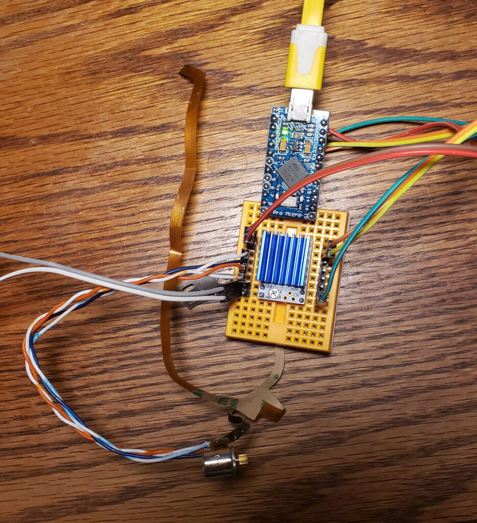
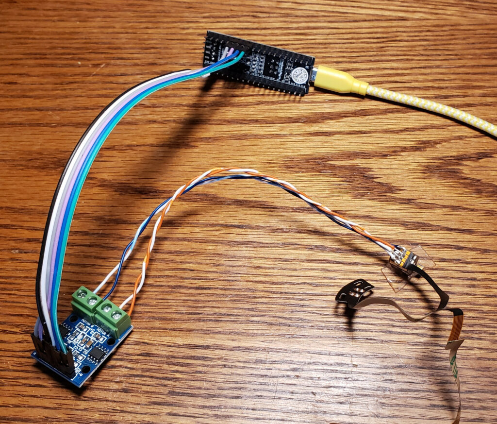
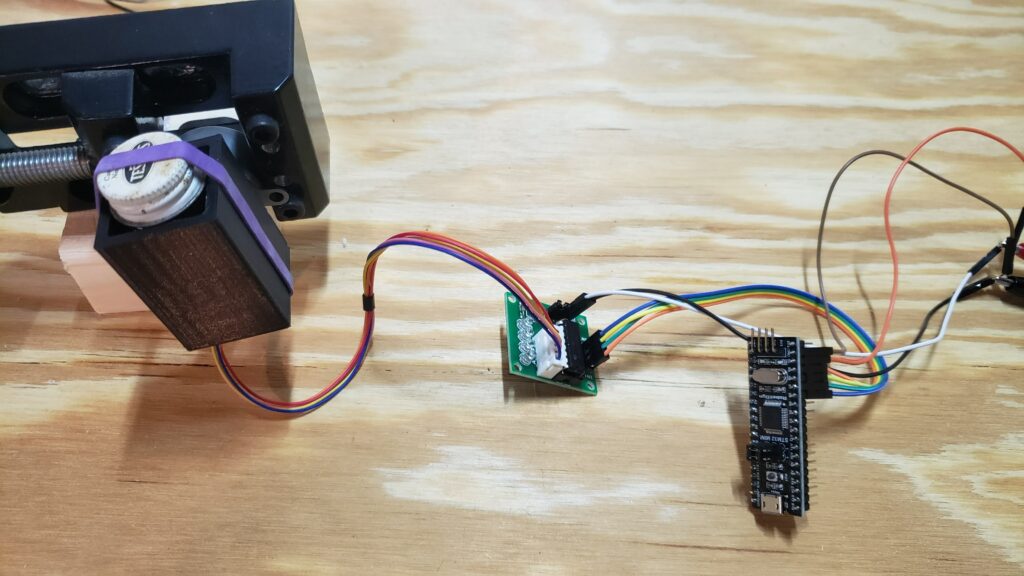
Test setup for one of these steppers
To get around the lack of documentation, I probed one out with a DMM then built a test rig out of a dual L9110S H-Bridge board and a little STM32F103 dev board with the AccelStepper Arduino library to figure out the details.
They appear to be 20 steps per revolution motors, though they seem to work noticeably better with a half-step drive pattern. They work nicely at 3.3V, but get a little hotter than I’m comfortable with if energized for an extended period of time; I also tried 5V and it seems to tolerate that fine as well, gain a noticeable amount of extra torque, and get appreciably louder.
I don’t have the tools around to easily test the effective torque, but was way more than I expected based on my experiences with other small hobby motors. In my little taped-to-the-table test setup (pictured), if I jammed a fingernail into the rotor when it was already at speed at around at about 1000 steps/s on a 5V supply, the motor and/or nail deflected rather than missing steps.
Motor Diagram
If you look at the motor with the output shaft facing away from you and label the four pads A,B,C,D, the phases are A-D and B-C with about 9Ω across each phase.
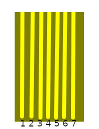
FPC Connector Pinout
If you look at the attached flat flex cable with the end pointed toward you, it has 7 contacts. For reference, let’s refer to them numbered 1-7 left to right. The ribbon itself is 4mm wide, and the contacts appear to be 0.5mm pitch, so it would probably mate with any of the various “7Pin 0.5mm Pitch FFC FPC” connectors floating around on the market for cheap if you wanted to spin a driver board for it that used the included cable.
The last 4 cable pins correspond to the motor terminals 4-D, 5-C, 6-B, 7-A… but for experimentation it’s easier to just solder leads directly to the motor pads. I used two pairs out of some old stranded CAT5, visible in the top picture.
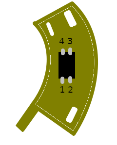
IR Reflective Object Sensor Breakout
There is a bonus component on a little arc-shaped boardlet built into the flat flex. It appears to be some manner of reflective infrared optical sensor, which I assume was used to establish a home position in whatever these were designed for use in – frankly since it has convenient mounting holes and wiring it would be pretty nice to use the same way in most applications I would want one of these in.
The first three ribbon pins are attached to this part, and none of these pins are shared with the motor itself. For discussion, let’s number the pins 1,2 left to right on the side toward the flex cable, and 3,4 right to left along the other in typical IC fashion. The pins are broken out Part 1 = Flex 1, Part 2 = Flex 2, Part 3 = also Flex 1, Part 4 = Flex 3.
Two of the pins (+ on 2, – on 3) appear to be a diode with a 1V forward voltage, and after I thought about it and checked with a camera with a bad IR filter, it is an infrared LED. The other pair seem to be a phototransistor or similar; it reads about 1.5MΩ from pin 4 to pin 1 in darkness and 1KΩ across the same with an IR LED pointed at it.
I’m not sure what I’m going to do with these, but they seem promising for small motion systems, especially since (if I bought bulk packs of each from China) you could get the motor and pair of H-bridges to drive it for under a dollar. Hopefully I’ll run into something to play with them in and/or my reversing work will enable someone else’s cool project.
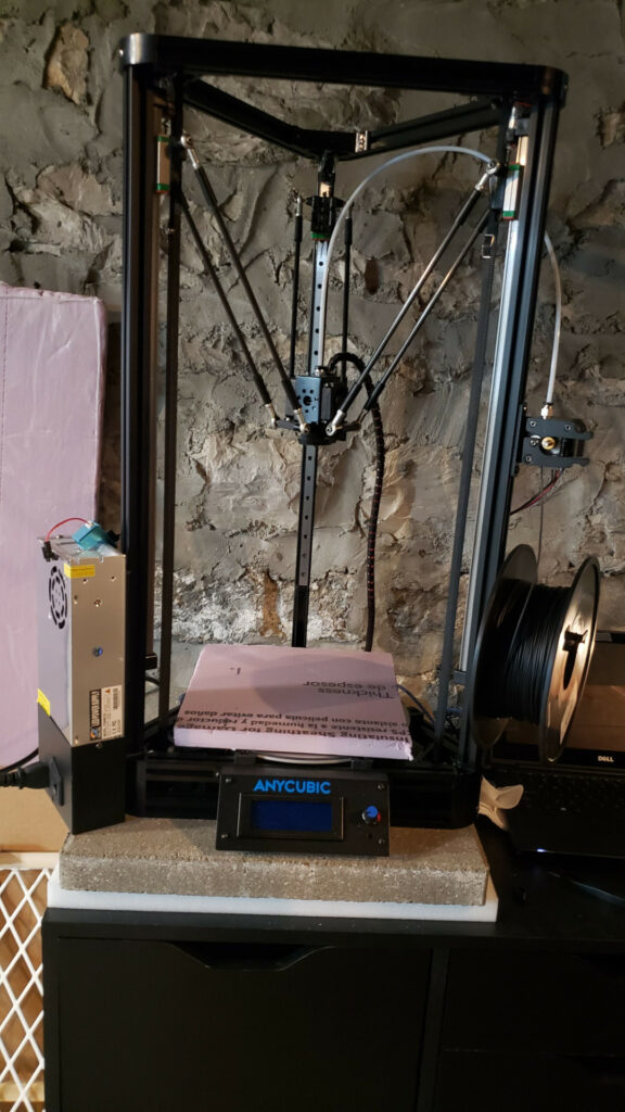
I’ve had an Anycubic Linear Kossel for several years now, and have generally been quite pleased with it – if Anycubic were still selling them I’d still be suggesting them as ideal first printers.
It has produced quite a number of useful pieces, a decent assortment of household conveniences, and the usual selection of toys and meme trash for myself and others.
I’ve made a couple recent upgrades that seemed worth documenting.
As I continue my electronics part organization spree, I was looking for …something… reasonable for through-hole resistor storage. Resistors are a problem because there are a lot of values, once mixed they’re possible-but-irritating to distinguish, and strips of resistors are awkwardly shaped.
There are some special-purpose drawers, most of which aren’t very flexible (configured to hold exactly the E12 series, or with slots too small for the 4″ strips a lot of cheap resistors come in, or…), and many of which are enormous 3D printing projects in their own right that I didn’t feel like dealing with. There are some systems with small or card-catalog style drawers, but I don’t stock large enough quantities of resistors to invest that kind of money/space, and don’t plan to. I also looked at variations on schemes using card holding binder pages, since I really like the cheap SMT binders (link is the ones Adafruit stocks, mine are all the ubiquitous brown ones with gold-debossed Chinese text because I’m cheap), but after I bought a pack of the appropriate business card slot binder sheets I realized I’d underestimated my size requirements.
After quite a lot of looking around and stalling, the only thing that really appealed to me was cloning Zach Poff’s Edge-Labeled Baggie Method, so I did.
I added some E24 values (like 51x and 75x) that I had stocks of from one purchase or another, and a few other odd labels that I happen to have stocks of. The added labels are missing the cute little colored resistor images because I’m not sure how they were generated and it wasn’t urgent enough to spend a ton of time on – I just put the value and the band numbers on those.
I did cheap out on basically every part; I used 2mil 3×4″ baggies instead of the nice 6mil ones, and I used AmazonBasics 1 x 2-5/8 Inch labels that list themselves as compatible with Avery 5160 labels. Both of those may eventually prove to be a mistake, but for now they work and feel fine.
One thing I am looking to improve upon, I currently have them stored in an old Kroger deli meat tub, which is OK but not ideal. I don’t think I can find something that will hold them reliably and still clear the 3″ height of the drawers I’ve been packing a lot of my component assortments into, so I’m probably looking for something that will close, possibly a large-ish 3×5 card organizer.
I’ve been doing some component stocking lately, and haven’t really set up a solid storage system, so I picked up a Harbor Freight 40+1 drawer cabinet thing to manage various small size + small quantity parts.
There are slots in the drawers to take dividers, but Harbor Freight doesn’t sell them, and Akro-Mils charges a bit much – somewhere in the vicinity of $10/16pcs – for injection molded dividers that experience says don’t fit terribly well. The set of Akro-Mils drawers I use on campus for kitting out instructional labs has first-party dividers that tend to float just enough to get pins trapped under them, which leaves me less than enthusiastic about spending money on those.
I saw some folks 3D Print their own, but always feel silly 3D printing flat parts, and wanted something clear.
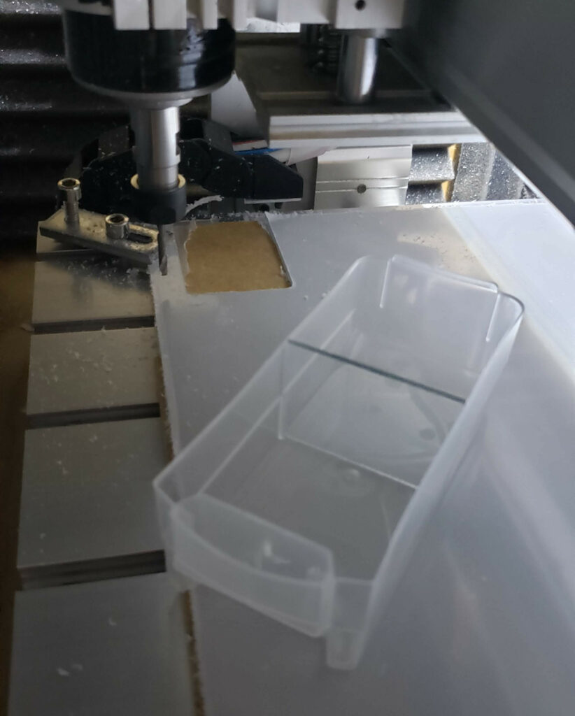
..So I took some measurements, ordered some 0.078″/2mm polycarbonate sheet, and CAD’d up the shape.
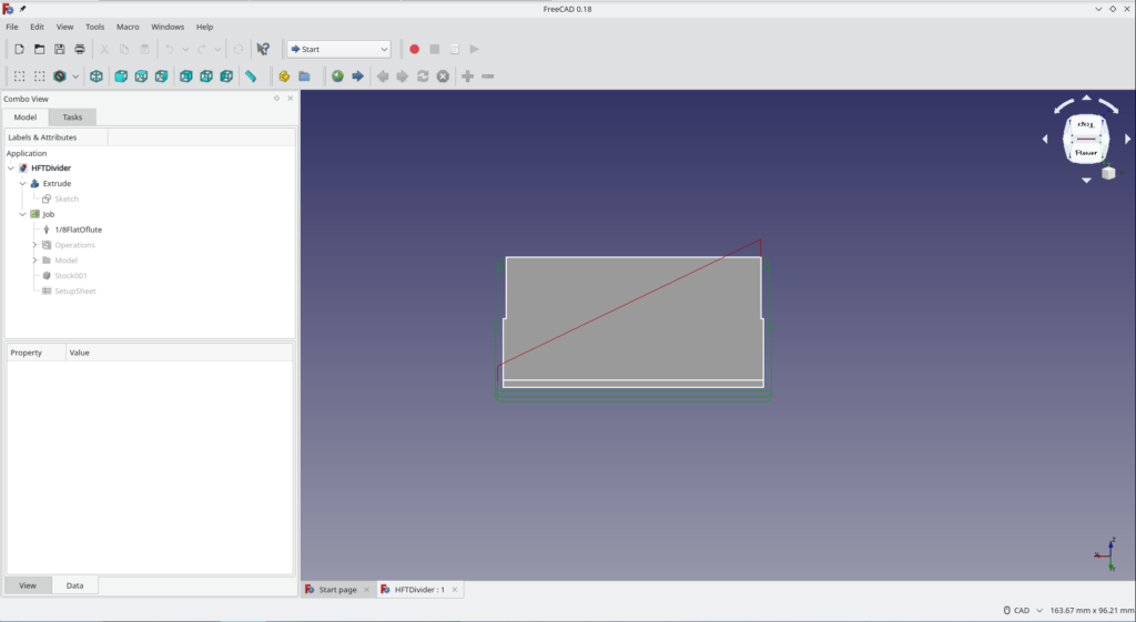
I did a quick parametric sketch/extrude/profile in FreeCAD 0.18, and unlike the last couple times I tried to build something in FreeCAD, the Sketch constraint system didn’t bug out, the Path workbench didn’t crash, and it posted reasonable gcode. I am very pleased by this development.
Now, it is a trivial part (rectangular, 2mm thick, 34mm tall, 50mm wide for the bottom 17mm, 51mm wide for the top 17mm), but I had earlier versions of FreeCAD fall over on similarly-trivial projects, usually in the path workbench. I’d really like to have (and be vaguely competent at using) a decent all-FOSS design flow for the router, so this is an exciting development. File here if anyone wants it.
There was the usual CNC fuckery (losing Z steps because I plunged too aggressively for the bit, tapping the Z- stop because I had the spindle raised in its clamp for working off a vise and forgot, etc.), some of which were solved by finally switching my Z axis motor to a slightly higher current since I keep having problems with running out of Z force.
Had I looked a little closer I would have noticed there are third party laser-cut acrylic dividers available for like $0.33/ea compatible with the Akro-Mils small drawer size, but if you ignore the …$1000-odd of CNC machine and tooling and the value of my time… these come out to like $0.16, so it’s not completely absurd from that angle, and it was a good tool-chain test. Also, happily, they fit significantly tighter than the Akro-Mils injection molded ones, so no trapped pins.
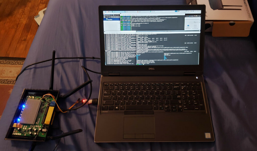
I’ve been running a TP-Link Archer C7 flashed with OpenWRT at home since early 2016 (and a TP-Link 1043ND with OpenWRT for years before that), but since I moved into my current place over the summer it has been falling over every couple weeks. It hasn’t been logging anything (I have a flash drive mounted that it persistent logs to) but goes down until hard reset, most likely just because of the load of two heavy stream/video-conference/file-sync users (…and probably not because of my kitten chewing on the antennas. Probably.) Rather than updating/diagnosing I decided that was a good excuse for a new faster router.
TL;DR: The Asus RT-ACRH13 is an excellent current-production OpenWRT host for ~$65 with only minor install challenges, and represents a significant upgrade over the Archer C7.