TL;DR: If you have one of those sketchy Chinese metal-cage 500W spindle speed controllers that uses a potentiometer for speed control, the potentiometer terminal block is probably referenced to a dangerous voltage, be careful what you connect to it and/or replace it with a less dangerous one.
I only intermittently have the time and energy to play with my little CNC router, but the later part of this summer has been devoid of overwhelming obligations for a rare change. I’ve been taking the opportunity to to get back up to speed with it, with the rough objective of learning to quickly turn around single-layer PCBs.
One of the standing TODO items on my machine for the last …at least five years… has been that the probe ground would give you a small shock if you touched it. That is generally considered “not good.” The PCB work I’m looking to get better at involves a lot of careful probing, and works well with the super simple tool-to-conductive-workpiece method that gives lots of opportunities to catch a shock off the probe wires, so I decided it was time to find and fix that problem.
I went hunting fixing grounding problems; I added an earth lead to the frame (to make sure it can’t float up), I earthed the case of my spindle controller (which is an older model that doesn’t have an earth terminal), I replaced my sketchy no-earth-reference 12V wall-wart with a proper metal cage supply with a proper chassis earth, all of which were good ideas that didn’t cause any problems and increased safety … and none of which actually fixed the “getting shocked” problem.
I then tried tying the DC negative of the 12V rail (that supplies the pullup to my probe) to AC earth – the wisdom of which is the subject of some debate – to see what would happen and it made the spindle run up to full speed un-commanded, even with the E-Stop breaking the enable connection, which is a pretty good sign that my sketchy spindle controller setup was at fault.
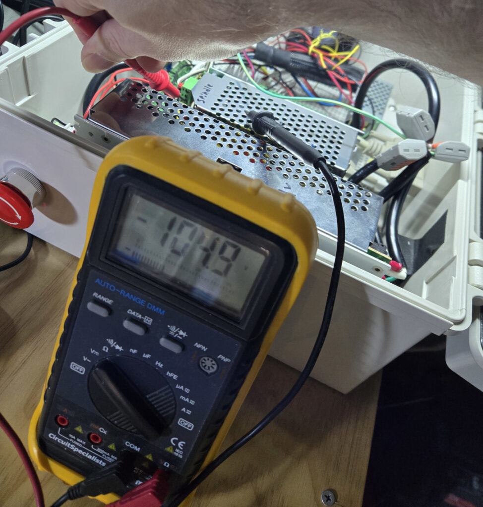
The spindle and controller I’ve been using is one of those China-export-special 500W air-cooled ER11 brushed DC sets with a 52mmD body, 100V rated motor, and frightening un-earthed, un-branded metal cage supply/controller, whose speed control is accomplished with an included potentiometer. I installed it a little creatively and ran my 0-10V speed control output between the potentiometer low and center pins, which works to control the spindle (if everything is isolated). I removed my DC- to earth connection and, a little more probing and a few unwanted sparks later, determined that the whole speed control block on my spindle power/control unit is referenced at -120VDC relative to supply earth, and has substantial AC leakage 😬.
Rather than trying to isolate the existing setup, I bought a new controller for $50, which has “advanced” features like an earth connection on the terminal block which is internally connected to the chassis, and an explicit 0-10V input. I went with this Daedalus branded 0-100V 500W unit on Amazon because it was cheap, quick, and appeared to match the features I was looking for.
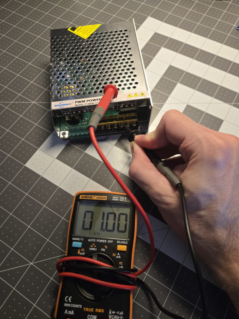
A straight wire-for-wire swap later (using the dedicated 0-10V control inputs), everything seems to work as intended, and there are no major potential differences between any of the control grounds and earth to catch a shock off of. The spindle is also noticeably quieter; I think the waveform the old one was producing was chopped in an ugly and/or lower frequency way that was causing vibration.
