
Between having more disposable income and the potential for upcoming trade weirdness, I’ve been pretty fast-and-loose about buying random bullshit that catches my fancy from China of late.
A recent Aliexpress order consists mostly of USB tampering supplies, like an exhaustive set of breakouts for all the common USB connectors, including a couple extra type C breakout boards because I’ve been doing a bit of Chromebook abuse recently and a SuzyQ cable is likely to come in handy.
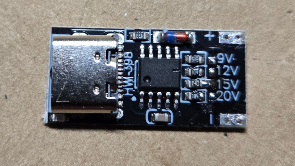
In that batch, I also picked up a 10 pack of these little HW-398 USB C PD trigger boards (aka Decoy boards). They have a USB C Female connector on one end, + and – pads on the other, and a series of little pads marked with voltages that you can solder bridge to an adjacent resistor to have it negotiate that mode – apparently via any of the PD/QC/AFC protocols for doing so.
They seem like they should be useful for powering projects from easily obtained junk, but merit investigation because they also seem a little sketchy and were a whopping $0.63/each.
A couple of the behaviors and design decisions are interesting:
- The USB C connector is slightly inset on the PCB, which is probably good for strength, but rather unfortunate for mounting it into a project.
- They DO supply 5V when none of the higher values are selected, which is both reasonable and desirable.
- There is a little blue indicator LED next to the plug, and it’s marginal at lower voltage.
- It appears if you set a voltage not supported by a supply, you get the next voltage down, which I gather is suggested by the standard. This is not unreasonable but has real potential for unwelcome surprises if you don’t protect your design. The most likely issue seems to be a lot of supplies don’t support the optional 12V mode: I didn’t thoroughly test, but I popped one strapped for 12V onto a little Anker 313 whose label says 5V@3A,9V@3A,15V@2A,20V@1.5A and it delivered 9V.
- The IC is conspicuously unlabeled. It’s an SOP10 package, and is smart enough to do to necessary USB negotiations (which are actual USB protocol traffic performing a handshake to read and write some control registers at either end). A little googling seems to imply the chip is a Fastsoc FS312 – It’s in the right package, supports PD,PPS, and QC negotiations, which lines up with the product description, and the setting straps are connecting resistors of values 184(180kΩ)=20V, 140(14Ω)=15V, 104(100kΩ)=12V, 513(51kΩ)=9V which matches the datasheet.
- I haven’t done any load testing, but I don’t see any sign of regulation on the board, so I suspect the regulation will depend entirely on the supply.
- I have no idea if the USB IF considers these legitimate.
It certainly seems like a useful gadget for the parts bin. LCSC doesn’t seem to stock the FS312 IC, which is a shame since now that I know they seem to just work with the very minimal suggested circuit in the datasheet that requires only a capacitor and resistor beyond the chip and connector, I’d start designing them into boards if I could get them stuffed by the usual scumbags.

nice information
Has this trigger a diode or any other protection against current coming from the output side so it can be used to charge a custom (e.g. 12v) battery?
Apparently not. There is a diode that looks like it should provide reverse polarity protection, but probing it out, it doesn’t seem to actually do anything. The – contact is definitely straight through to ground, and the + contact is straight to Vbus in either polarity.
Thanks for the reply.
So a battery with more than 5 V will definitely need a diode to protect chargers and other USB devices that might be connected.
Thanks for the information! I got my hand on several of these but they refuse to output 12V, even though my supply supports it via PPS. Instead, it gives me 9V which is probably the result of using only PD. From the FS312 datasheet, it can be forced into PPS mode by connecting GP0 to ground (it was wired to 3.3). I simply cut off the pin and it seems to work and give me 12V while in floating, though adding a blob of solder shorting it to ground might be wise.