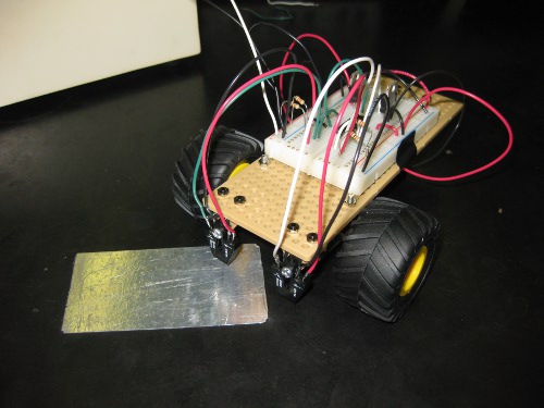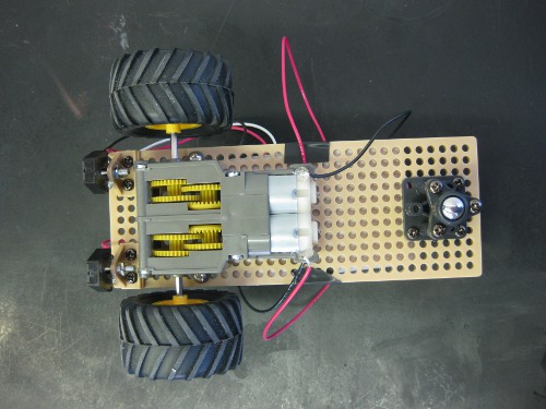
This week we did the lab the parts in my New Teaching Robots post were for, and it was very much a “mixed success” sort of situation. I put a test chassis and circuit together about a week and a half ago, and modified the sample solution from the crappy old cars to work with the new ones, and that was reasonably successful, although it did exhibit a little bit of sluggishness and jitter, which, in retrospect, I should have taken as a warning sign.
Last week we had a build party to put the chassis together, so that interested students in the class, as well as other people interested in robotics, could come play with the parts (and perform the repetitious part of assembling a small fleet of identical machines). That event was quite successful, resulted in a collection of 6 mostly complete chassis, and a lot of enthusiasm. I even had one student build a circuit to ensure that would be reasonable, and that went well.

For the lab, we told students upfront that it was an experimental new lab they were participating in the design of, rather than something routine they were simply expected to perform. This was a good call, as it immensely with investment in the activity, and to reduce frustration when things didn’t work as planned for reasons outside of their control.
There turned out to be three basic problems with my design for the lab:
– In our enthusiasm for the new cars, both the faculty instructor for the course and I forgot that the protoboard power supplies usually used in this lab don’t tolerate the >1.5A spikes from driving substantial inductive loads well. This was a major compounding factor, and the most likely cause for the sluggishness I observed in the test case. This was fixed for the last section (there are nice 4-channel 5A variable output supplies in the lab), which helped alleviate some of the flaky behavior.
– I seriously overestimated the fabrication skills of most of the students. They haven’t developed what I consider “natural” design practices as far as physical layout or EMC, so constructing physically and electronically robust circuits on the small section of breadboard attached to the backs of the chassis was out of reach for many of them. I was very hands on with each group once the problem became clear, and had the latter two sections build some parts of the circuit off-board with suggestions, but it was still an issue.
–

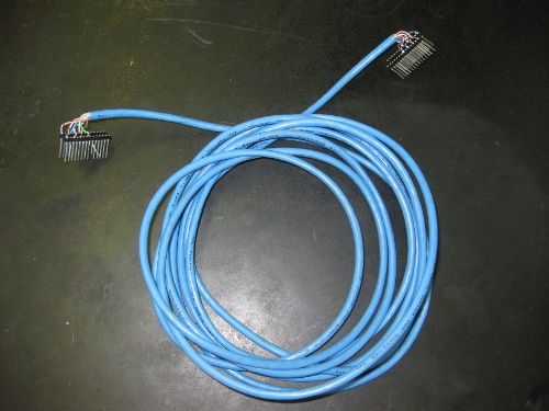
6+ feet of Cat5 cable (twisted pairs) carrying ~5V signals switching at various speeds in the 0-100kHz range are one hell of an electromagnetic echo chamber, and I didn’t adequately account for that in the design. I’m still not sure how much of the strange behavior this can be blamed for, but there were sufficient effects to require substantially different passive components depending on which end of the cable which section of the circuit was built.
The latter two problems could have been alleviated, and the first one discovered much earlier, if we had stuck with the original plan to have PCBs milled and pre-assembled for all the discrete components, with fixed cables for attaching the FPGA boards the state machines were designed on. Hopefully at some point in the not-too-distant future there will be a chance to get that done for next semester.
Despite the problems, all the students were engaged, and a lot of them stayed and played with their design even after we told them they had done enough to be counted as completing the lab. In terms of educational outcome, we lost the excitement of making something which can move around reliably on its own (except for several groups who set up simple wired feedback from the sensor to the FET while they finished their sate machines…), but in explaining the various ways in which things went wrong, gained brief, simple, practical exposure to concerns in drive systems, emc, fabrication, and at least half a dozen other topics they will be taking courses in over the next two years. Most importantly it exposed students to some of the process of engineering whole systems, which is something one rarely gets until working on one’s own projects. I do wish it had gone as smoothly as the adder lab I replaced with a comparison of different adder designs (in Verilog) last semester, to introduce size/speed performance metrics, procedural test-benches, and the RTL/Tech schematics generated by ISE, while still teaching the basic lesson in binary arithmetic, but things did go surprisingly well for the level of unforeseen technical difficulties.
I feel almost as bad about spewing the above stream of awful loaded-meaning education jargon as the shortcomings of my plan, but there is no language I’m aware of for discussing the education process that hasn’t been co-opted by idiots.

