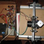
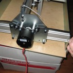
Naturally, this post is a follow-on to Shapeoko: Part 1 and Shapeoko: Part 2. I’ve basically put the machine together now, and can move the X and Z axis around from the host computer, but still have to figure out belt attachments for the Y axis, and run the wiring in a sane way. I was holding up a microswitch to the various relevant spots for end-stops as I went, and everything but detecting the upper extreme of the Z axis should be easy. As in the last two posts, there is an assembly gallery under the fold.
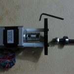
- Lay out the Z axis bits. 13mm wrench for the 8mm nuts, the same Allen wrenches that have been used throughout (the coupler uses the same size as the M3 bolts), and some removable thread locker.
- The instructions in the wiki are a bit unclear about where the M3 washers go, between the spacers and the motor face seemed most logical.
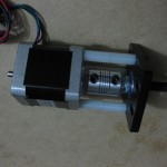
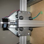
- Motor mounted. Keeping everything lined up while screwing it in is really rather unpleasant. It would be nicer to have ~1.5″ aluminum spacers that actually fit than a stack of oversize nylon bits rattling around, it looks like a pair of 20MM M3 spacers per screw could be swapped in pretty easily, but getting the full 1.5″ length would be difficult.
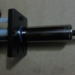
- There is a really nasty knick about 2/3 of the way down my leadscrew. I touched it up with a triangle file until all the relevant nuts passed over it without serious binding, but it really should have been wrapped for shipping so that didn’t happen.
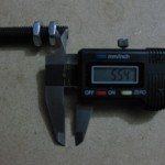
- As promised in the documentation, the only measuring you need to do during the build, and it doesn’t require much precision.
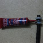
- I hit one of the jam nuts with a little blue loctite to encourage them to stay put.
- Now join the leadscrew to the motor assembly. This entailed a lot of fiddling to get things lined up and pushed into place.
- I used a larger socket to put even pressure around the outer race of the 608 bearing while shoving it in to place (trick picked up from cleaning longboards).
- Leadscrew and motor assembled. Bearing is (roughly) flush with the bottom of the plate, and protrudes a bit at the top. Nuts are (as closely as possible) trapped between the coupler and the bearing. Coupler has a good grip on both the shaft and the leadscrew.
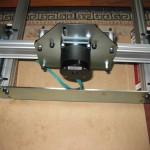
- Test-fit Z for sanity check, to make sure nothing is backwards or whatnot.
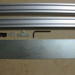
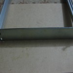
- Time to start framing. The parts for the belt anchor are in the picture, even though they won’t help me with my belt-on-the-outside setup.
- Get all the bolts into their holes, but don’t tighten anything down yet.
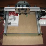
- Use a couple similar-sized books to rest the gantry on so everything can be lined up. The Bovet and Cesati Linux Kernel book might as well be good for something (get Robert Love’s Book for learning about the kernel).
- After loosely connecting the other plate, run the gantry all the way to one end and tighten it down while the gantry forces rough alignment.
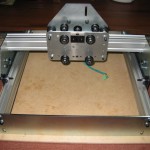
- Frame complete.
- The instructions talk about driving the Z axis on with a hand drill, but there is a perfectly good stepper motor attached, so hook it up (remember, phase pairs are connected through a couple Ohms of resistance, the other wires are not). All my motors are hooked up via very nice little quick-disconnect terminal blocks I got from some Chinese ebay seller.
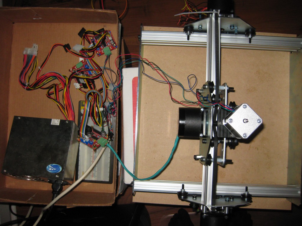
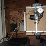
- World’s sketchiest setup. Shapeoko is resting on a stack of paper boxes, electronics are in the lid of a paper box on another stack of boxes. Connected to the computer (running the LinuxCNC Ubuntu reroll) via quick and dirty pin-header and cut cable parallel port breakout plugged in to breadboard. Powered from a cheap ATX PSU with the sense pin jumped to ground. Good enough to drive the Z axis into place and do a bit of testing.
- And on she goes. There was a little binding at the nicked spot on the screw, relieved by jogging it across a couple times. I’m not super pleased with how much the motor/leadscrew wobble, but the Makerslide seems to be staying straight once the V-wheels were snugged up. I guess this is why someone has started selling an acme-thread upgrade kit.
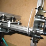
- First pass X belt tensioner, using the provided little metal strips and a ziptie on each end.
- My motor wires are way too short, but extending is easy. Just hooking up to get a rough test of my LinuxCNC settings.
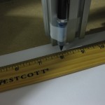
- Using a pen tip and ruler as a primitive indicator, the settings are basically right on X and Z (10x.1″ moves is actually an inch, backlash is small and almost certainly the fault of my sketchy first-pass tensioning job, etc.). There seems to be a slight tramming issue (bed is higher at one end of X travel), but it isn’t even screwed down yet.
- Next challenge is attaching the Y belts.
I have various bits of aluminum around from previous projects to work with, it shouldn’t be too hard to hack something together – I’m currently fiddling with some scrap plate and some U-channel to try two different arrangements, I’ll probably iterate a couple times on one side, then duplicate the winner to hook up the far side. Dragging an idle motor (please to call it “counterweight”) shouldn’t hurt anything, right?

