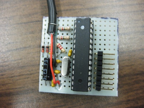
It took over a year for me to get back to it, but I finally sat down and made some progress on hacking the Buttons Pionier was giving away at SC09.
When I last posted about it, I had drawn out all the USB identification information, as well as disassembled one, identified all the hardware components, and tracked down data sheets for the important bits.
Now that I have a Bus Pirate, I decided to dump the 24c64 EEPROM. A 24c64-type EEPROM speaks standard I2C, with the addition of three dedicated address pins (for banking chips), and a hardware write protect pin.
My first attempt was a little troublesome, because attaching the chip in-place was (as is often the case) powering the whole board, leaving two I2C bus masters, and confusing the situation.
The following is basically a reference for communicating with 24c32/64 EEPROMs.
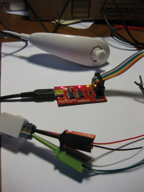
To remedy the problem, I simply desoldered the 24c64 from one of the buttons, soldered pins 1-4 (one full side) to a bit of wire, so I could ground GND, A2, A1 and A0 with a single clip, and attached the bus pirate leads to the floating chip (Yes, SOIC8 packages are rather small):
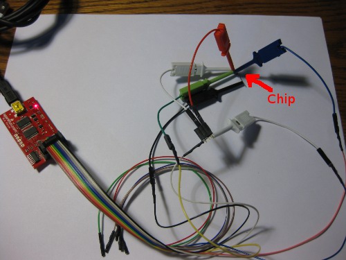
To be specific the connections are GND to pins 1-4 (Gnd, A2, A1, A0) 3.3V to Vcc (8) and WP(7), CLK to SCL (6), and MOSI to SDA (5) like so:
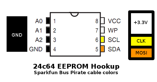
To write the ROM, the WP pin would need to be grounded instead of powered, but preventing writes is a good safety measure when exploring.
Software-side, I ended up following the communication instructions in the Bookly 24c64 datasheet, because I found them asier to interpret, but the datasheets from Atmel or any other manufacturers that make a compatible part will do as well. Start with the usual bus pirate setup of ‘m’ for menu, ‘4′ for I2C, Chose a clock (I used 100kHz for fear of interference from the long-for-I2c leads), ‘P’ to turn on pull-up resistors, and ‘W’ to turn on the power supplies.
Then, to read out a 24C64, you feed it (this is a commented log of the terminal session)
I2C>[0xA0	-- Start, Send 1010, the Values on the A2-A0 pins (000 if grounded), Followed by 0 write for and 1 for read -- dummy write to set address pointer

I2C START BIT

WRITE: 0xA0 ACK

I2C>0x00	-- Send the start address to the chip, the 24c64 ignores first three bits. 0x0000 to start at the beginning of the ROM.

WRITE: 0x00 ACK

I2C>0x00

WRITE: 0x00 ACK

I2C>[0xA1	-- Starts, then random read (same as first byte of dummy write, with R/W high instead of low)

I2C START BIT

WRITE: 0xA1 ACK

I2C>r:255	-- Sequential read out the whole ROM (Overflows most terminal's history, I pulled 256 or 512 at a time.)

READ: 0x5A  ACK 0xA5  ACK...
I dumped it twice to cross-check that I didn’t make any dumb mistakes the first time, then massaged the dump with some regexes to get rid of the communication details and extract a pure hex dump. Only the first 4608 bytes of the ROM are written, so there is even room to tamper, if I can figure out the encoding. Note that the posted string is NOT S-records or Intel HEX, but raw ASCII-encoded two-characters-per-byte hex. In order to get it into an 8051 disassembler for further analysis, I will either need to figure out how to coax the Bus Pirate to generate a formatted dump, or write a script to segment and prefix the existing string, but neither has happened yet.
Giving analysis a first pass, I looked for pieces of the string it prints when activated as ASCII and raw USB HID Scancodes, but didn’t find them… which either means there is a problem with the dump (byte order?), or some clever and inconvenient encoding was used. I’m not terribly familiar with 8051s and their associated tools, so that will be the rather large next step. If nothing turns up in analyzing the dump, I may have to sniff the bus while the board is in operation to see if there is some funky data layout obfuscation.


