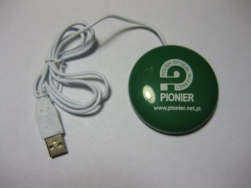
(eventually I’m going to have to hack up a light tent (for the glare) and camera mount(for the jitter) for this kind of thing, but it hardly seems necessary with my little point-and-shoot)
One of the more promising bits of schwag at SC09 was a little USB button thing handed out by Pionier. The basic premise on the button is that after connecting it to a computer via USB, it lights up with enticing shifting colors, and, when pressed, sends the computer to the pionier SC09 website. It does this by announcing itself as a USB HID device, emulating a keyboard, and typing “{control}rhttp://www.pionier.net.pl/webstarter/09scpo6r8q {newline}”, which will have the desired effect… from the desktop on a windows box. After seeing what it did on a laptop on the show floor, I grabbed a few extras thinking they would be fun to hack.
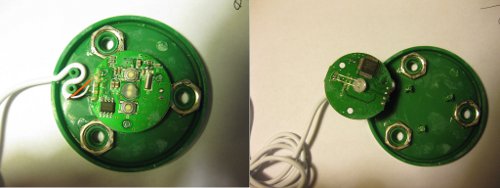
I pulled apart one of the buttons to read off what the chips are, and things look promising. (larger image linked)
The board is based around a MXT8208 USB 2.0 Flash Disk Controller (datasheet). The chip consists of a 80c51 microcontroller with hardware USB 2.0 PHY, I2C, a general purpose UART, some dedicated flash management features, and 28 GPIO pins (mostly overlapped with other functions) in a LQFP48 package. This means it SHOULD be susceptible to much better hacks than simply changing the output string; with a little luck it will be convertible into a darling little intermediary device for attaching projects to a computer via USB by serial or PIO. Since there is no flash chip hooked up, the majority of the GPIO pins are free, making it especially suitable for that kind of repurposing. By far the primary use for this chip is making little USB flash drives (and, based on the information around the ‘net, this one is particularly favored in making “fakes” that misreport their capacity, because it is more programmable than many of it’s competitors), but, assuming I am interpreting the chinglish datasheet correctly, the non-memory USB widget use case here is intended as well. Matching the suggestion in the datasheet, the software for the button behavior is (apparently) on a K24C64 64kbit Two-wire EEPROM (Datasheet) mounted on the other side of the board.
The other components aren’t terribly interesting: a pair of SMT push buttons, a 12Mhz crystal, 6 assorted SMT capacitors, 3 assorted SMT resistors, and a 2-lead RGB color phasing LED(unfortunately, 2 leads means it probably can’t have it’s behavior altered beyond on/off).
Software wise, it reports VID=0×2000, PID=0xbeba, which seems to be a made up ID written to the chip in software. There is a UdTools utility offered up by micov (after a little bit of google translate-foo), but it only seems to be able to tweak the flash-specific functions, not perform general reprogramming. This IS promising, as it implies everything should be writable from a host computer, rather than having to pull the EEPROM and program it separately to alter the behavior, but I haven’t figured out how to do so yet.
Any ideas? Usage wise or tools wise?


Pingback: Bus Pirate! | PAPPP's Rambling
Pingback: Pionier Button Hacking: Step 2 | PAPPP's Rambling