I got some more time to work on my Shapeoko over the last few days, and now have mostly correct 3-axis motion. As before, details under the fold.
After I mentioned on the forum that my leadscrew had issues, I took Edwards’ suggestion and dropped an email to Inventables. They continue to be amazing, and shipped me a new one with no questions or charges. The replacement showed up promptly, has no knick to cause binding, and walks noticeably less. I know from experience (clearly shared by many of the RepRap folks) that that kind of all-thread will never be anything resembling straight, but this one seems to be within the range that the helical coupler can handle. (No pictures, repeat of the process last time – and I’ll have to do the fiddly step again because I put the motor on with the wires facing in a dumb direction).
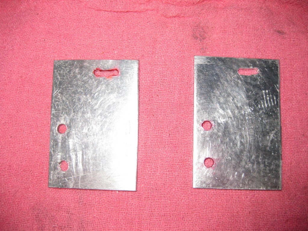
With the leadscrew settled, I dealt with the Y belts. I went at some aluminum sheet (1/8″ 6061 sheet, IIRC) from the previous CNC project with a hacksaw, 13/64 drill bit (5mm is ~.197″, 13/64 is ~0.203″, it’s almost perfect for passing 5MM thread through), 1/8 drillbit (to set up the slot), a hand-held drill, and some hand files to build a passable set of brackets for the outside configuration belts.
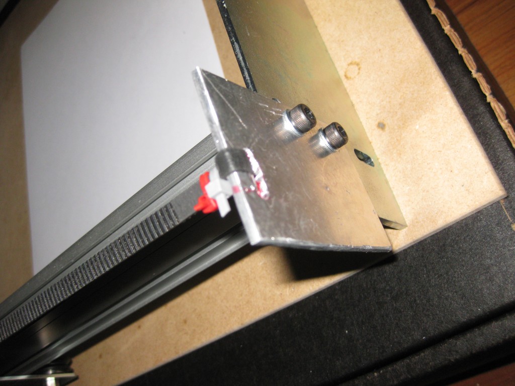
I didn’t have any suitable transfer punches (ideal would have been some 5MM transfer screws to make it perfectly match the beam, but nope), so I roughed the hole alignment by marking through the holes on one of the endplates. Between that and the hand cutting/drilling, they are not straight, and one required a bit of filing of the screw holes to fit at all, but they seem to be good enough. I’m using the Zip-tie method for closing the ends of the belts, the teeth bite into each other well enough that I don’t see any reason to do otherwise.
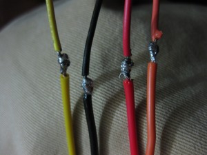
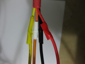
All my wires needed extending, and I wanted to keep the color code, so I cut the harness off a dead ATX power supply and harvested the appropriate wires. The PSU leads are 22AWG, which is a little chunky, but it worked out nicely. Those aren’t the world’s best inline splices, but they are cross-wrapped. I also have a bunch of colored electrical tape in my wire bin for coding, so I kept the colors mostly consistent there too.
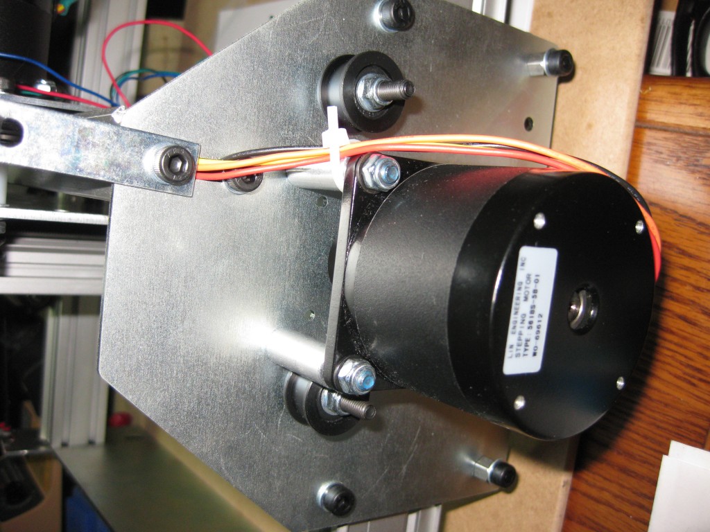
I still need to hook up the second Y motor – it is currently installed, with the wires run neatly through the X axis makerslide, but with no belt or electrical connection, so it is basically a counterweight at the moment. I’m partly holding off until I’m settled on belt hardware.
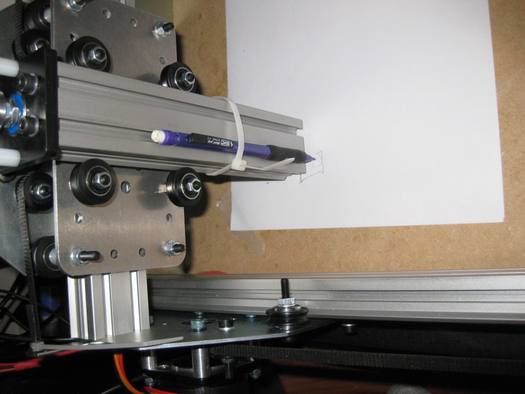
First 3-d Moves! I started with a pencil because it fit nicely and doesn’t bleed or the like, but the wearing of the graphite makes it hard to get a good line. The “E” is the first character of the EMC built-in test writing, if you look closely it is Y-flipped. I briefly played with a sharpie (and damaged the tip and bled ink into a stack of paper in the process) after that, before settling on a ball point.
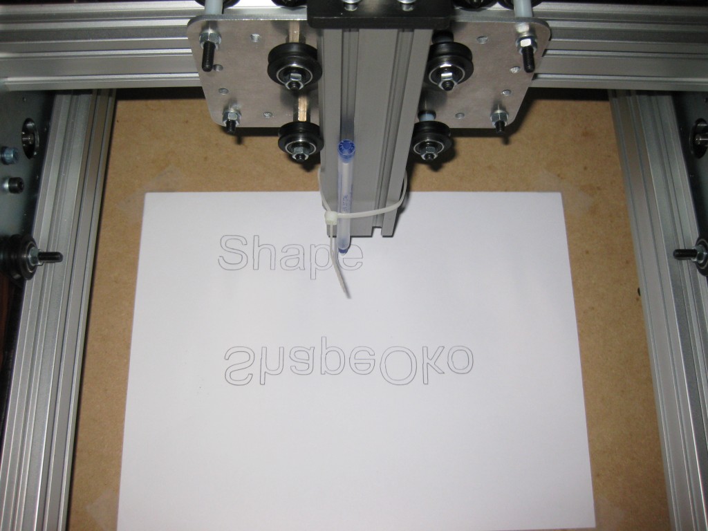
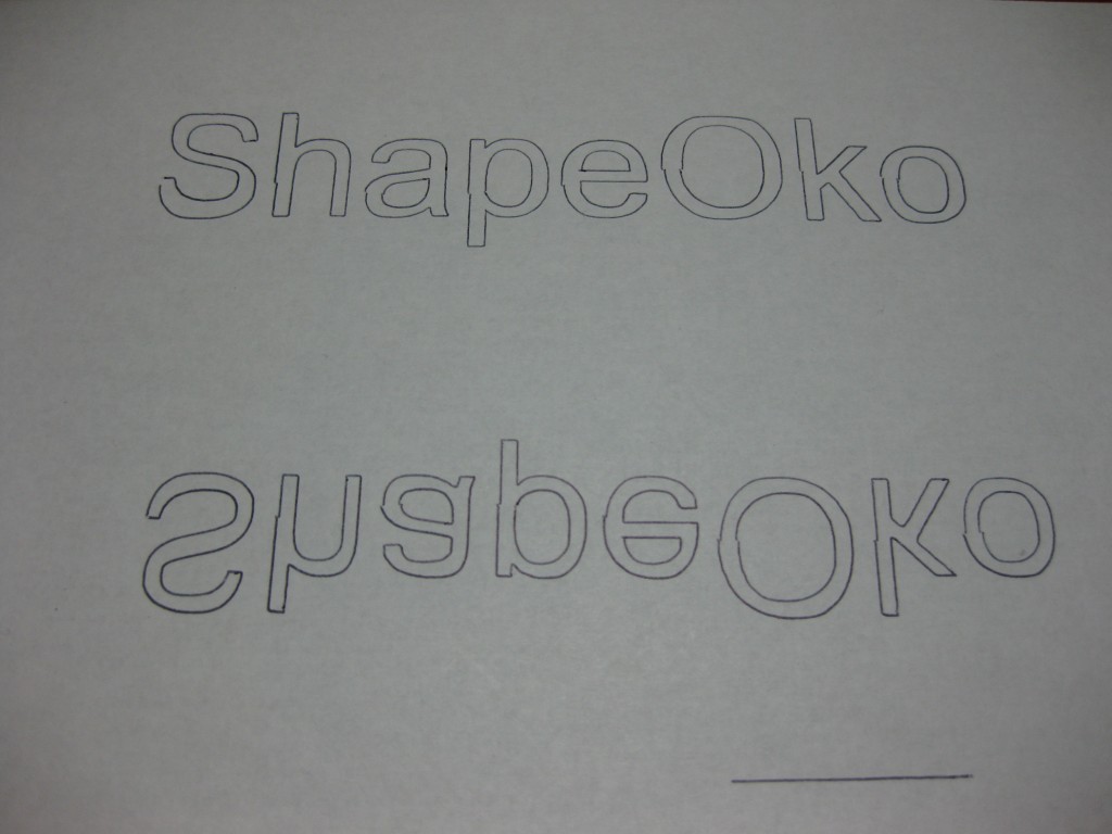
The standard Shapeoko Hello World program, with a ballpoint pen on Z. You may note the first one is Y flipped because I changed things in multiple places trying to get my direction and reference both how I wanted (which in hindsight was dumb, what I was aiming for isn’t a quadrant of a sane Cartesian system). Still haven’t fully figured the machine specification stuff out, LinuxCNC has a reasonably slow but very deep learning curve. Second run has all the axis agreeing on coordinates, but is still a little off.
The current issue appears to be belt tension – I’m reading that misalignment along the center line of the Shapeoko hello world text partly as slop from taking up belt slack, and partly because I had too much flexible pen body extended past the Z slide. The slight flattening at the top of the right-side-up text appears to be because running at the very end of the range introduces badness, maybe because my belt height is a bit off.
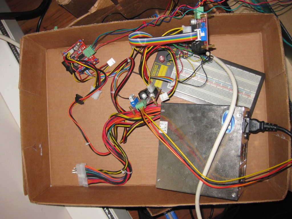
Once all the electronics are figured out I need to build a more reasonable wire harness, with terminals and secured parts and probably optical isolation, the current box of wires tied together through a breadboard arrangement is fine for testing but nasty and fragile.
I’d really like to design and fabricate some nicer belt tensioners. At present I’m deciding how well I like my current design – I have the material for more, but want to make sure they work well before investing the time to make another pair. It would be fun to cut a full set of nice ones with the Shapeoko (have it build its own upgrades), although I’m not sure I’ll be set up to cut aluminum with it by the time I want them, and cutting aluminum will almost certainly make enough of a racket and mess that the machine would have to be relocated to somewhere not my apartment for the job (or run inside some sort of enclosure, which is another project that sounds like fun).
I’ll probably make 4 pretty copies of whatever I settle on because the current pair is quite ugly, and I like symmetry. I also have some other designs in mind in case I decide there is something unacceptable with this one, many of which can be made from (mostly) on hand materials.
I’m quite sure I want to put endstops on so I don’t have to watch it so closely and can do automatic homing. I have a bag of micro switches, and am thinking I’ll stick them on with phone wire and double-sided adhesive pads initially.
I also need to figure out a spindle, I have a couple rotary tools around but none of them fit the included brackets well. I’m thinking I’ll visit Harbor Freight to rig something cheap and limited initially, then suck it up and get one of those couple hundred watt Chinese ER-11 spindles and associated drive electronics once I’m comfortable with the machine.
This thing is a bottomless source of fun projects, which is precisely why I wanted it.


Pingback: Shapeoko: Part 6 | PAPPP's Rambling