Between having more disposable income and the potential for upcoming trade weirdness, I’ve been pretty fast-and-loose about buying random bullshit that catches my fancy from China of late.
A recent Aliexpress order consists mostly of USB tampering supplies, like an exhaustive set of breakouts for all the common USB connectors, including a couple extra type C breakout boards because I’ve been doing a bit of Chromebook abuse recently and a SuzyQ cable is likely to come in handy.

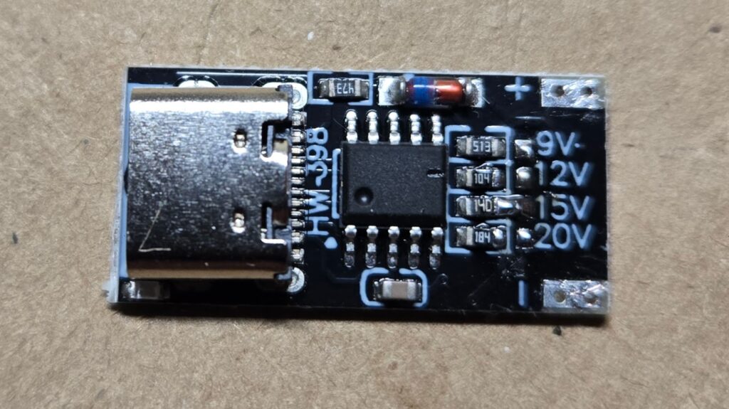
In that batch, I also picked up a 10 pack of these little HW-398 USB C PD trigger boards (aka Decoy boards). They have a USB C Female connector on one end, + and – pads on the other, and a series of little pads marked with voltages that you can solder bridge to an adjacent resistor to have it negotiate that mode – apparently via any of the PD/QC/AFC protocols for doing so.
They seem like they should be useful for powering projects from easily obtained junk, but merit investigation because they also seem a little sketchy and were a whopping $0.63/each.
A couple of the behaviors and design decisions are interesting:
- The USB C connector is slightly inset on the PCB, which is probably good for strength, but rather unfortunate for mounting it into a project.
- They DO supply 5V when none of the higher values are selected, which is both reasonable and desirable.
- There is a little blue indicator LED next to the plug, and it’s marginal at lower voltage.
- It appears if you set a voltage not supported by a supply, you get the next voltage down, which I gather is suggested by the standard. This is not unreasonable but has real potential for unwelcome surprises if you don’t protect your design. The most likely issue seems to be a lot of supplies don’t support the optional 12V mode: I didn’t thoroughly test, but I popped one strapped for 12V onto a little Anker 313 whose label says 5V@3A,9V@3A,15V@2A,20V@1.5A and it delivered 9V.
- The IC is conspicuously unlabeled. It’s an SOP10 package, and is smart enough to do to necessary USB negotiations (which are actual USB protocol traffic performing a handshake to read and write some control registers at either end). A little googling seems to imply the chip is a Fastsoc FS312 – It’s in the right package, supports PD,PPS, and QC negotiations, which lines up with the product description, and the setting straps are connecting resistors of values 184(180kΩ)=20V, 140(14Ω)=15V, 104(100kΩ)=12V, 513(51kΩ)=9V which matches the datasheet.
- I haven’t done any load testing, but I don’t see any sign of regulation on the board, so I suspect the regulation will depend entirely on the supply.
- I have no idea if the USB IF considers these legitimate.
It certainly seems like a useful gadget for the parts bin. LCSC doesn’t seem to stock the FS312 IC, which is a shame since now that I know they seem to just work with the very minimal suggested circuit in the datasheet that requires only a capacitor and resistor beyond the chip and connector, I’d start designing them into boards if I could get them stuffed by the usual scumbags.

