I’ve been fascinated with machine tools and mechatronics for well over a decade, and have been indulging that fascination with a series of little benchtop CNC machines since about 2008, especially since my collection of related degrees lend legitimacy to my desires. Because of my other lifestyle choices I’m more or less restricted to a machine which is small and well-behaved enough to operate in an apartment, is roughly man-portable, and fits in normal vehicles, at least for the time being. Possibly fortunately, this restricts me from going off the deep end and buying a small VMC, or even building out the heavier classes of benchtop machine.
Last year I started to feel like my old V1 Shapeoko (ca. 2012) was not really usable as a machine tool – it was a good toy, and I learned a ton of cool things from it, but it wasn’t stiff enough, reliable enough, or laid out in a way that made it practical to use for much of anything. After I had my Shapeoko on campus for a demo day, my adviser was inspired to buy himself a complete package Chinese 3040 CNC router, and I got a chance to play with that for a few days. I wasn’t terribly impressed with the electronics on it, but the frame proper impressed me enough that I decided I wanted one as an upgrade.
…So near the end of the spring semester, I ordered myself a bare 3040Z frame and a pile of parts to kit it out. The machine is built almost entirely from inexpensive Chinese components, purchased via a mixture of Aliexpress, eBay, and Amazon sellers (I’ve become fond of uxcell for small parts). I don’t have accurate or current price quotes for the whole thing because I bought as I went, and various parts are reused from previous projects. I suspect the total is in the neighborhood of $1200 – comparable to buying a slightly more powerful finished system without the enclosure or limit switches.
It was my intention to write this up in sections as I built it out, but kept opting to play with work on the machine instead of doing more writing – particularly since such a large part of the things I’m supposed to be doing with my time of late are also writing. I finally got the last of the major parts “done” to my satisfaction a few weeks ago, so it’s time to gather the pictures and notes from what should have been half a dozen topic posts and make a gigantic brain-dump.
Mechanical

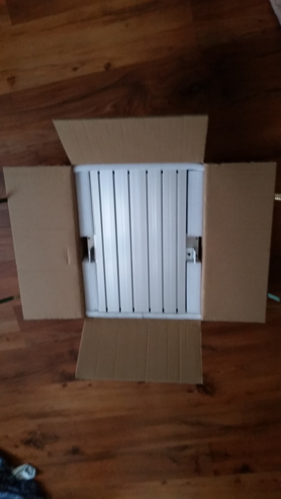
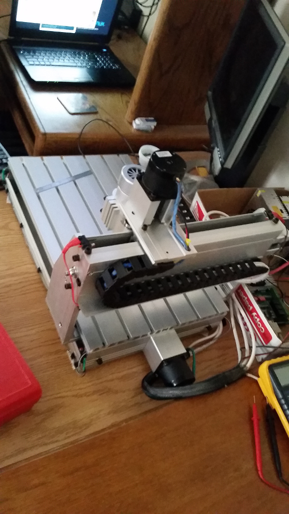
The main chassis is a typical Chinese 3040Z frame purchased for $447 from rattmmotor101‘s ebay store. The “Z” denotes that it is built on 1204 ball screws which are super neat, theoretically helpful, and do appear to have backlash below the detection threshold of my cheap import measuring tools. The linear motion components are pairs of 16mm unsupported round rails on X and Y, and 12mm on Z. They’re not as stiff as they could be, but seem adequate for the system.
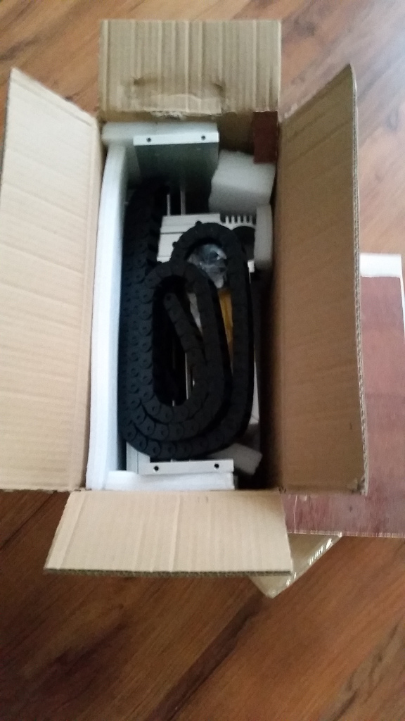
Everything came very nicely packed and quite promptly, and the finish and cleaning and such are slightly nicer than the handful of other similar machines I’ve had a chance to play with. It came in two wood and foam lined cardboard boxes secured with shipping straps, one containing the base, and the other the gantry and accessories. The gantry attaches with three M6 socket head cap screws on each side, two through the base and one into a piece of heavy aluminum angle profile.
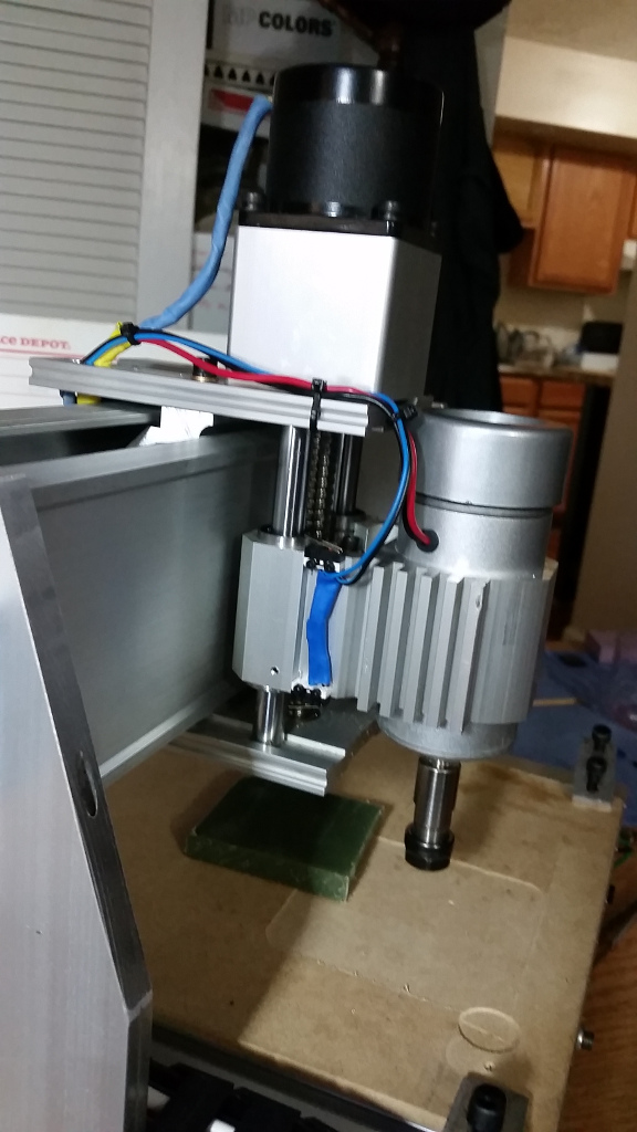
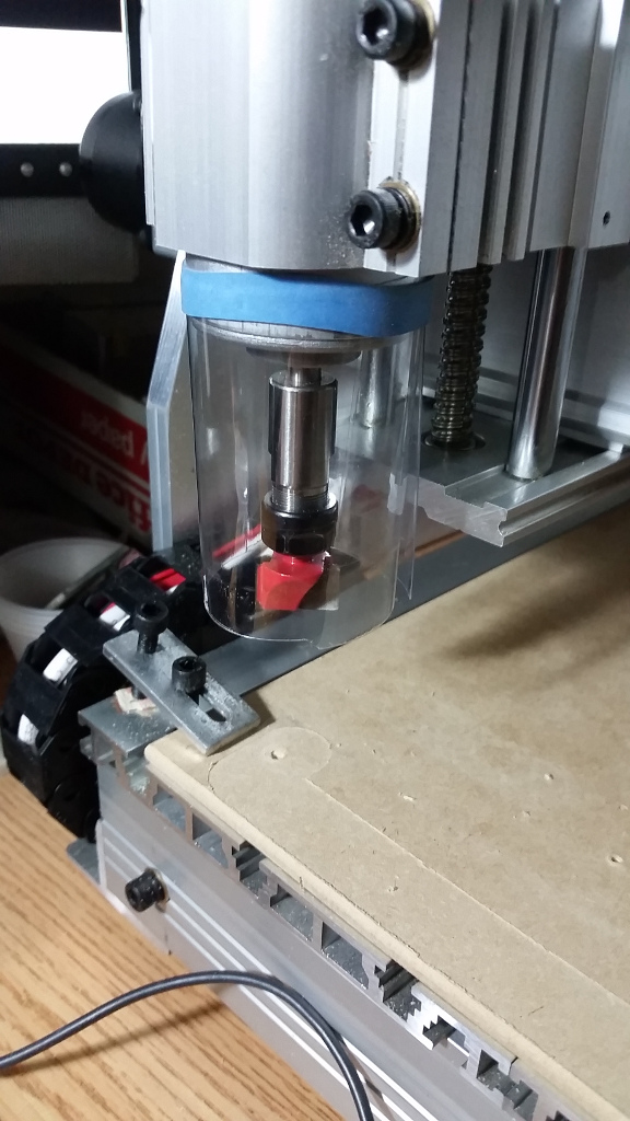
The gantry uprights are made of solid 12mm aluminum plate. The spars at either end of the Y axis are 12mm thick thick-wall hollow aluminum extrusion. The Z ends and spar to which the bearings and ball nut are mounted under the Y axis are all solid extruded aluminum profile, all approximately 12mm thick. The bearing pair and ball nut on the X axis are joined in a single large bearing block. Mine has the single-piece Z carriage with an integrated 52mm spindle mount, which appears to be one of the points of differentiation among 3040 machines. The rest of the assembly is thinner extruded aluminum angle. It may not be a serious metalworking machine, but it’s vastly superior to V-wheels and belts.
The slots in the bed open 8mm wide, widen to about 13mm for about 3-4mm, then narrow back in – they hold M6 square nuts or M5 insertion nuts, and seem to be some kind of standard, but I can’t figure out which. I haven’t found much fixturing to use with them, and am starting to think I’ll need to build some.
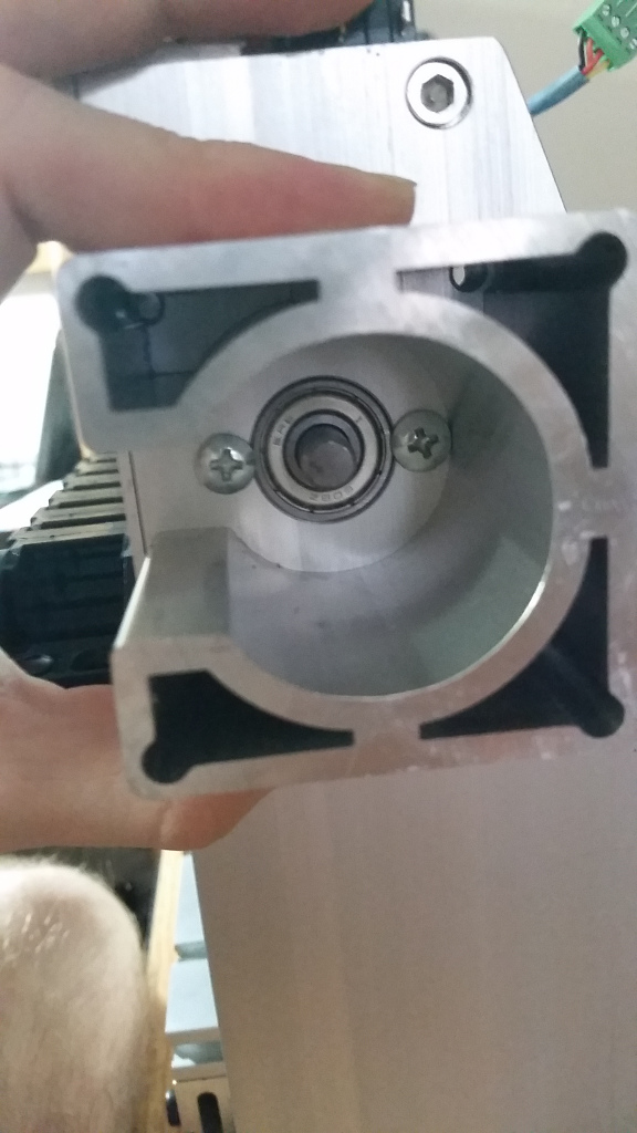
I dropped an extra $25 on a set of extruded aluminum motor brackets because I was afraid of flex in the plastic ones. They turn out to be slightly larger than the typical plastic NEMA23 mounts, which required ordering an extra batch of longer M5 screws and some fitting. They are, however, reassuringly stiff.
Wire Harness
I’m pretty pleased with the wire harness I built for this thing, it’s very tidy and professional looking by hobby CNC standards, and I’m pretty confident it’ll be robust.
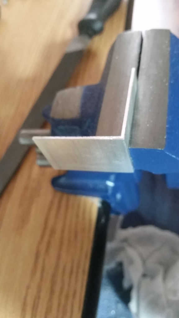
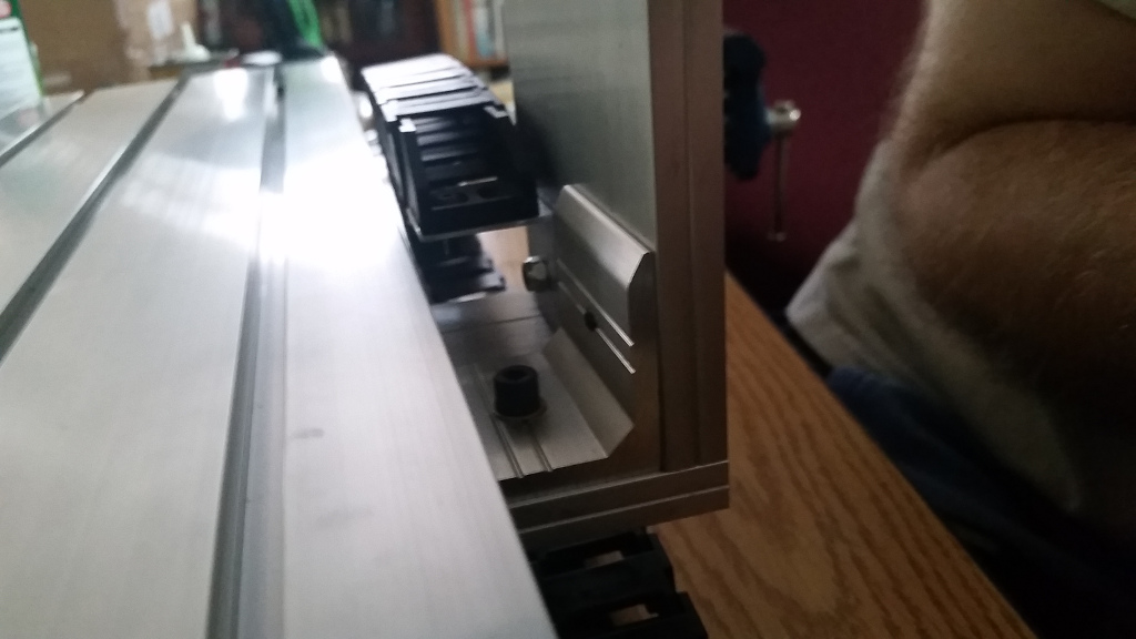
The frame kit came with a bunch of 15x30mm drag chain (as two 1m segments with ends) but no hardware to install it, so I ordered a bag of M4 button head screws, bodged a tab for where the Y chain joins the carriage out of a piece of 1″ aluminum angle with hand tools, and hooked them up.
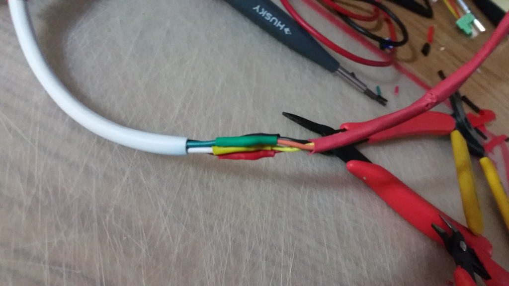
I did color coordinated (Red X, Green Y, Blue Z) heat-shrink and insulation throughout. The major wiring is done in Monoprice 18AWG speaker wire, in 4-conductor for the steppers and 2-conductor for the spindle, bought for the purpose. I also dug some finer gauge two-conductor wire in matching colors to use with the limit switches out of my parts bins. All the cables are snaked through the drag chains, slipped through channels in the aluminum frame, or adhesive-hooked out of the way. All the cables run to a common point at the (Xmin,Ymax,Zmin) corner of the machine, where they are bundled into a piece of 1/2″ expandable braided sleeving. In the final assembly, that umbilical snakes up the back of the machine enclosure, through the top, and into the electronics cabinet.
Limit Switches
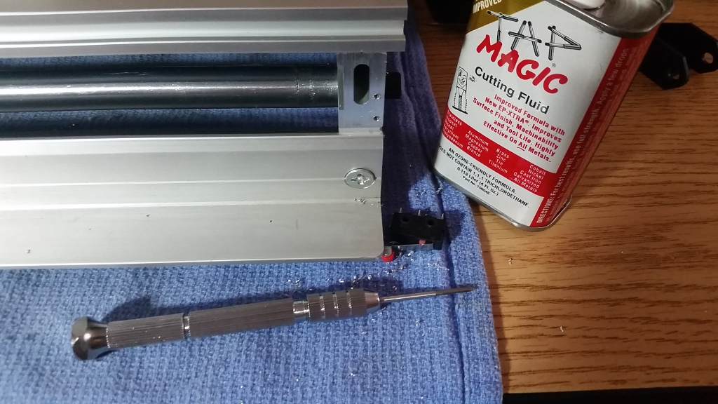

Only a few of the 3040-type machines I looked at online come with limit switches, and that is, in my opinion, a significant deficiency. I spent a lot of very satisfying time drilling tiny 1.6mm holes and tapping for M2 bolts to install switches at the ends of each axis, which I use for both endstops and homing. Having a repeatable machine zero is awesome, and having a bit of insurance against several of the more serious classes of fuckup is great as well. The pictures online of other’s attempts at installing endstops to a 3040 frame were not particularly promising, though I think I saw someone else who used the same approach for X as I did, so I essentially planned it out by holding switches in different positions and moving the machine around until I was satisfied – some of the positions are so suitable it’s hard to imagine the designers didn’t think about them. That strategy essentially worked, though I did end up doing the Y endstop install twice, because I had a brain fart and installed them in the path of the drag chain the first time, and had to redo the process on the opposite side of the machine. Because my breakout board only has five protected inputs, the max and min switches are wired normally open in parallel on each axis to save pins.
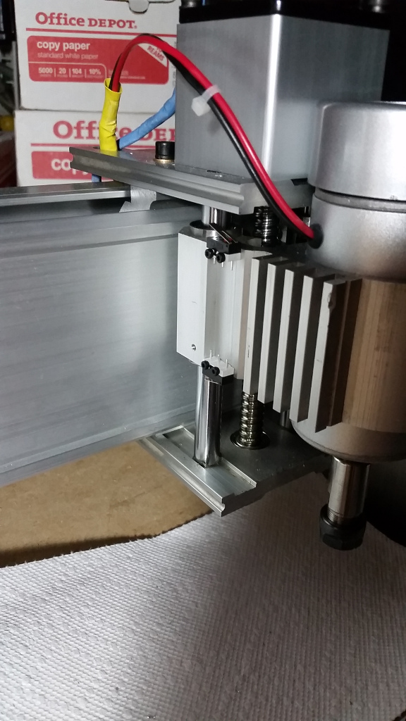
I initially only put switches on X and Y, chiefly because fitting standard 20mm long microswitches in to the Z axis was clearly not reasonable. After a couple close calls I decided Z really did need switches. I found and ordered a pack of the tiny subminiature 12.5×5.5x10mm kind, which nestle neatly behind the bearing block on Z, so I now have switches on both ends of each axis. I did slightly move the Z bearings inside their sleeves in the process of lining the Z switches up, but it didn’t seem to hurt anything. It’s possible that was a good thing, the bearings were at full extension to the top when the machine arrived, which was not ideal for maximizing travel or switch setup, and the bearing setscrews tightened nicely once I realized they were there to adjust.
Calibrated off the switches, I have a reliable working volume of 282mm in X, 375mm in Y, and 72mm in Z with a few millimeters of margin on X and Z, and 8mm of back off on Y. The back off is because it is designed to cantilever the spindle slightly off the end of the bed at Y minimum, which didn’t seem terribly useful.
Electronics
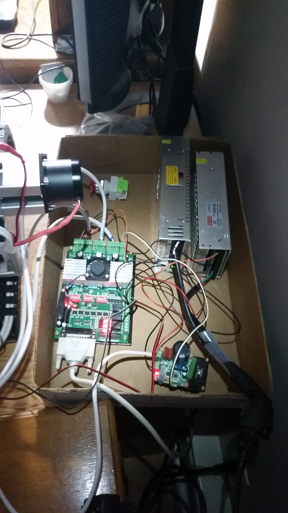
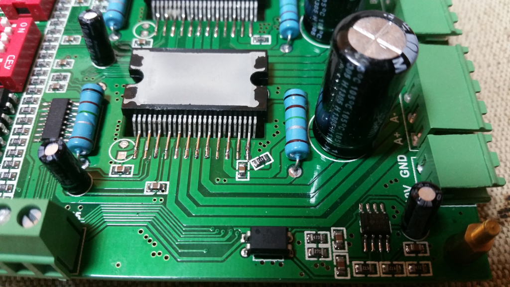
The electronics are based around one of the 3-axis TB6600 driver boards (the “Green solder mask” kind) which includes complete optoisolation for the DB25 connector, the obvious trio of TB6600 stepper drivers (one of which had to be reflowed because of a bad joint from the manufacturer…) with detachable screw terminal outputs, three relays with both the NO and NC contacts exposed, a PWM output, and 5 inputs with a reference ground. Omc-Stepperonline had the nicest manual for these boards, I’m rehosting a copy of their manual for this 3 axis TB6600 board since they seem to have taken the product page down, and deciphering the pinouts and jumper settings from the Chinese vendor documentation is not fun. I have the control jumpers on all three axes set to 011101 for 1.6A per phase and 1/8 microstepping, which has been smooth and powerful enough so far.
I’m reusing the same old set of contract overrun Lin Engineering 1.8°, 2A, 130oz/in NEMA23 motors I’ve been using in all the generations of little bench-top CNC machines I’ve built. Some of the commercial 3040 outfits come with stronger motors, but these have thus far been powerful enough, and I suspect they will be plenty unless I get ambitious and switch to something with feedback.
The other major commercial electronic component is one of the ubiquitous GBJ2510-based PWM controlled DC motor drivers, mounted to a suitably ginormous heatsink. This is the same controller (and spindle) that I had installed on later iterations of my Shapeoko setup. I’m only driving a 300W spindle, which is probably the weak point of the machine, particularly since it has so little torque. There are a couple nicer ER11 air-cooled spindles on the market now, including some fancy BLDC-with-feedback options, so a spindle upgrade may be the next item on the equipment treadmill. I think my particular frame design limits me to 52mm diameter spindles, but I can work with that.
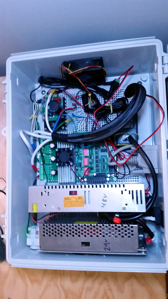
The bulk of the electronics volume is occupied by power supplies, as this is a three power supply design. A 24V metal-cased supply handles the stepper driver board and motors. A separate 48V metal-cased supply powers the spindle, and both supplies are cabled with nice ferrule-tipped adequate-gauge stranded wire – though some of the places I planned to use spade connectors turned out to be better without. All the 12V components are powered from a wall-wart, which is strapped to the backing plate on it’s back, plugged in with a pair of spade terminals clipped around the plug tabs, which are coated in heatshrink to avoid exposed 120AC. The 12V power is distributed via 5.5×2.1mm plugs along a splitter cable.
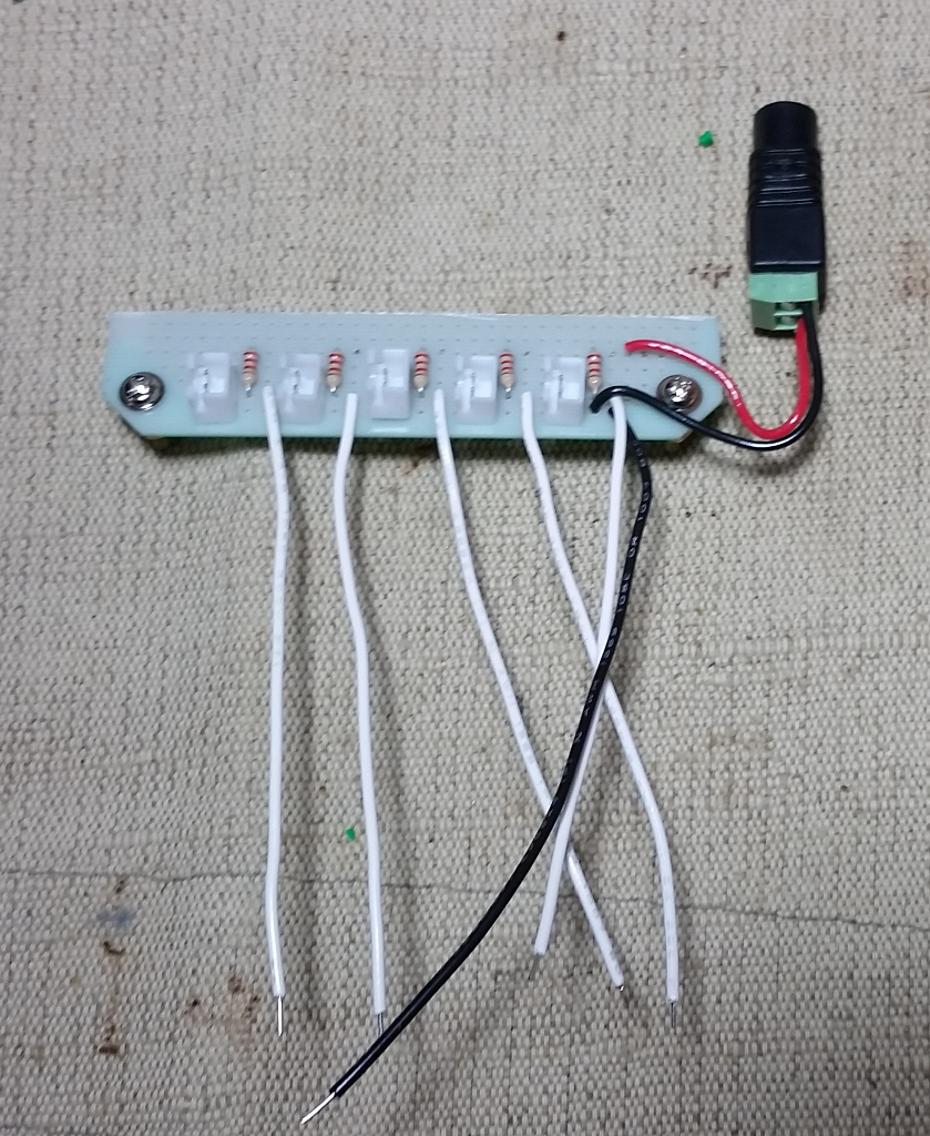
Before I built out a proper enclosure I had a small section of breadboard hiding in the pile of electronics providing 2.2KΩ pullup resistors for the limit switches. I replaced this with a section of perfboard with a JST-XH connector and pullup circuit for each of the 5 inputs supported by the breakout board, though I only currently have 4 connected (Combined ends for X,Y,Z, and the E-Stop). At some point I may use the 5th for a probe, most likely a simple tool setter, but possibly a miniature touch probe if I get ambitious. The pullups are powered from the same 12V wall-wart as the enclosure lights and fan, as that was the lowest voltage on hand.
Electronics Cabinet
I decided to be proactively safe about the electronics, and get a real commercial electronics box. Based on several attempts at laying out my components I got an approximate required size, which lead me to overpaying for a BUD Industries “NBF-32026 Plastic ABS NEMA Economy Box” (Dimensions 15-47/64″ Length x 11-51/64″ Width x 6-9/32″ Height) and corresponding NBX-32926-PL “Plastic Internal Panel” (Giving an internal work surface of 14-1/4″ Length x 10-27/64″ Width). The various components are screwed to the panel with a mixture of M3 and #6-32 screws (The same varieties as in a PC case, to suit the designs of the various components), while the cables are snaked in to the cabinet via 25mm holes cut through the bottom of the box and panel, and into the machine enclosure. There are also cutouts in the walls of the box, two for 80mm fan grilles, one of which actually has an 80mm Vantec Stealth fan mounted in it and the other of which is just a shrouded inlet, one (slightly rough) cutout for a DB25 connector, one 22mm hole to mount an E-stop switch to the front of the system, and one rectangular hole to match the switched IEC receptacle. Making the wall holes in the cabinet was not particularly pleasant, my assortment of cheap hole saws worked well enough for round holes, but the rectangular holes were done with a mixture of rotary-tool-mounted single-flute plastic cutting bits, plastic-cutting discs, and hand tools, none of which worked particularly gracefully. Coming back to that E-Stop switch: for the first time I have a real, physical E-Stop presenting in an obvious location that cuts off the machine, so hurrah for safety.
I considered using aviation connectors on the side of the electronics cabinet for connections, but decided to simply run the whole bundle in from the bottom and avoid the extra connectors. This is slightly inconvenient in that the 4pos detachable screw terminals for the motors will not fit through the access hole intact, but it is more or less my intention that the electronics be permanently mounted to the machine enclosure.
I’m pretty pleased with how it came out, though there are a few slightly concerning spots in the AC side as far as stressed insulation and isolation distances and such, and the High-Side/Low-Side separation isn’t as thorough as I’d prefer.
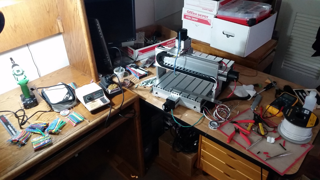
Machine Enclosure
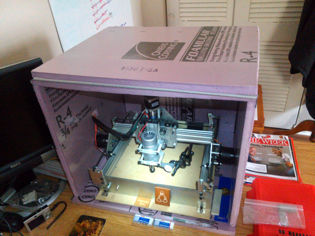
The machine itself is fully enclosed in an effort to suppress both noise and mess enough to let me run it freely in my apartment. My Shapeoko lived the latter part of its life in a cube made of EPS foam and duct tape, which was adequate for mess suppression, and helped for noise, but was not a particularly good piece of furniture(?) in my apartment.
I also learned from that setup that I really wanted something I could put things on top of, so having a table-like top was a priority in the new design.
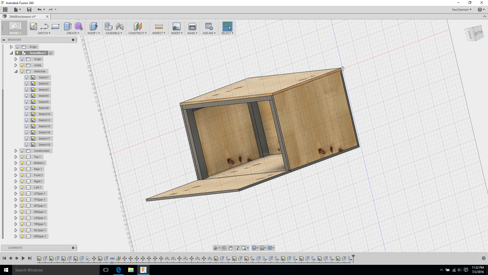
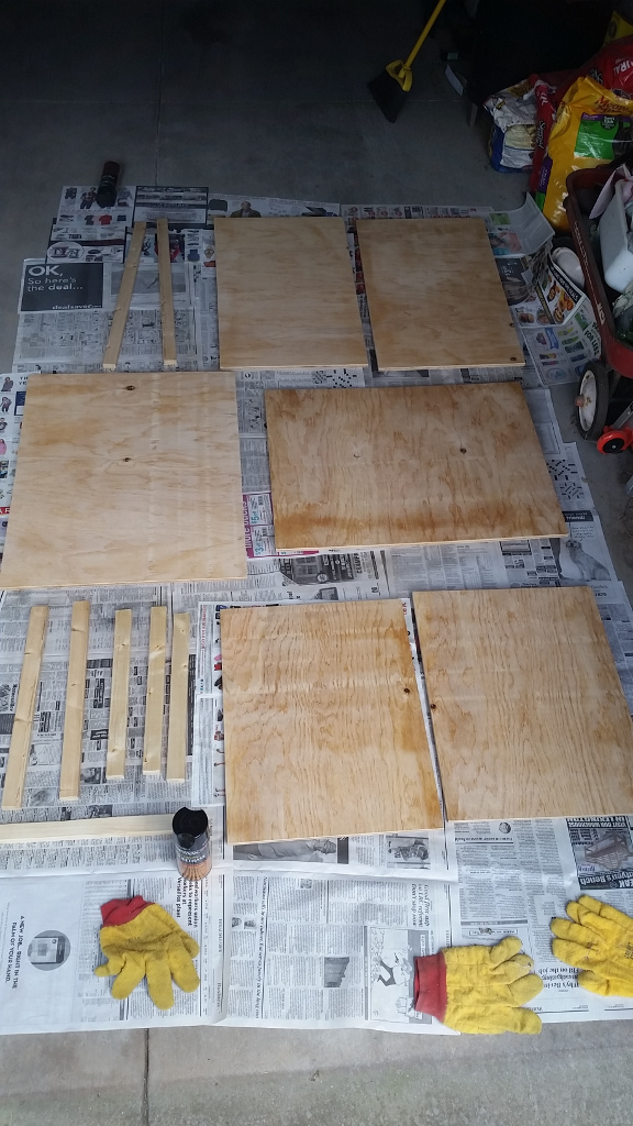
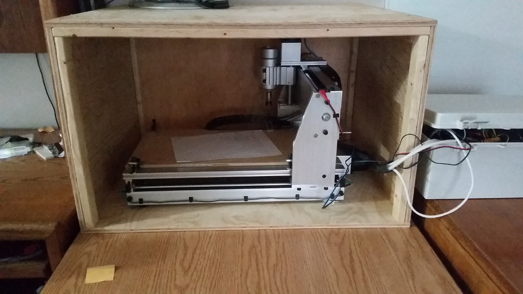
The 3040’s enclosure is built from most of a sheet of 1/2″ B-Grade plywood (Pretty-side out), and several sections of 2×1 to lend strength and provide a good place to put the screws. I CAD’d out the whole enclosure design in Fusion 360 to make sure all the clearances would work, plan out the sizes of my cut pieces, and generally figure out what I was doing. The design had no major problems, though finding suitable hinges proved to be a bit of a hassle, and the front-panel fitment is a little misaligned to suit the mechanics of available hinges.
The front folds down on a pair of hardware-store surface-mount cabinet hinges (installed with slightly cut-down screws), and locks up on a pair of cheap toggle latches. I have a pair of fairly heavy duty D handles that could be screwed into the upper support spars should I ever get the urge to move the assembled unit around on a regular basis.
The whole wooden assembly was finished in spray urethane, which turned out to be an expensive mistake – it costs something like $8 a can, each of which is barely enough for a single coat, takes days per coat to harden, and the 2-3 coats (depending on section) gave a thin, milky finish rather than the hard clear coat I was hoping for. If I did it again I’d most likely just suck it up and do a clear brush-on finish, one coat each before and after assembly.
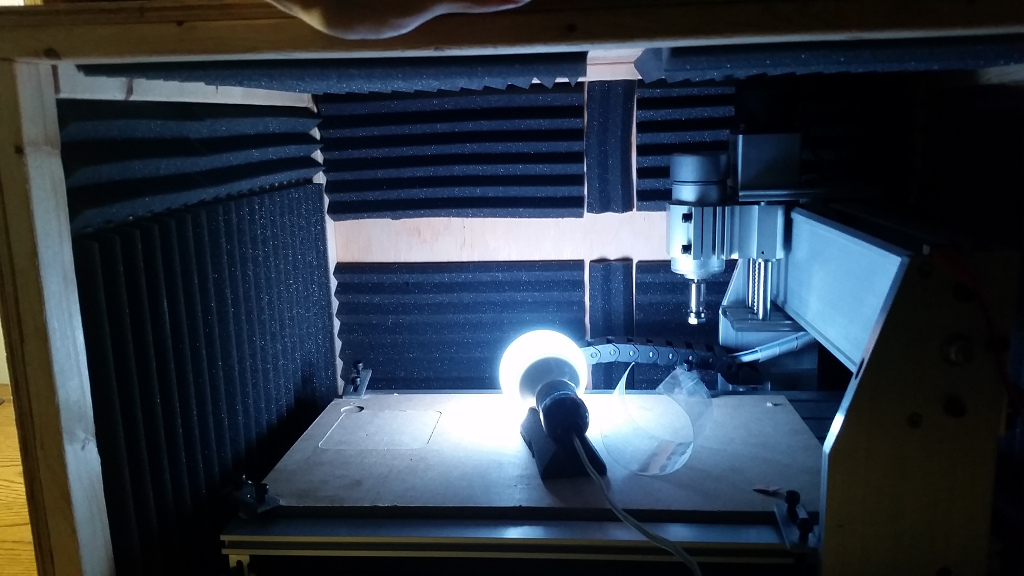
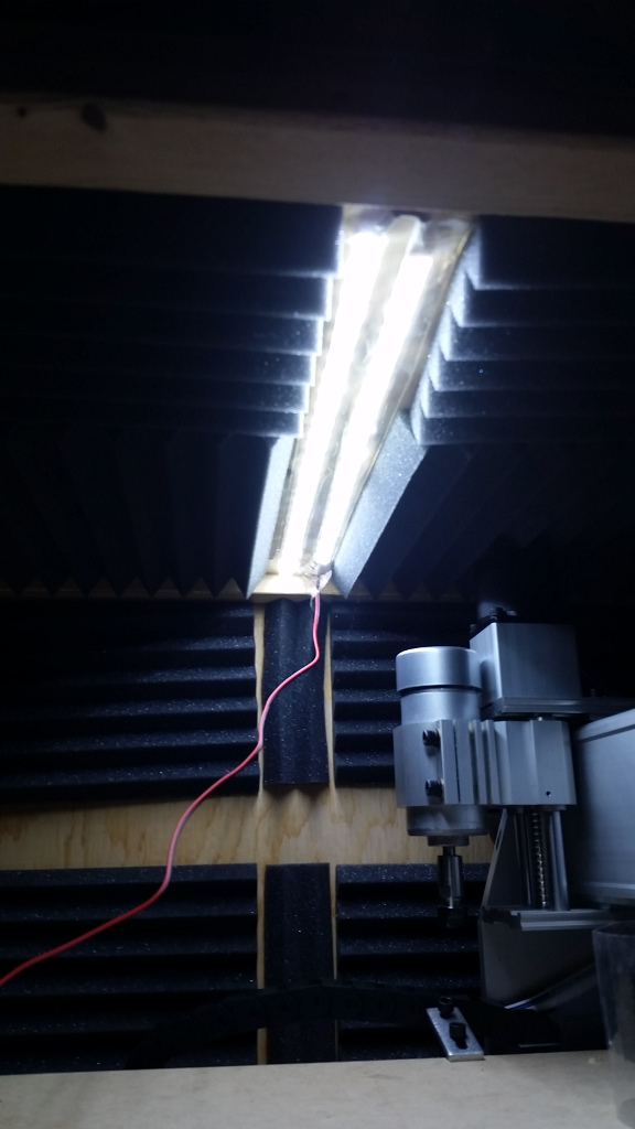
In an attempt to suppress noise, the inside of the enclosure (except for the door and a few clearance slots) is lined with 1″ acoustic foam panels. The foam is attached with 3M 45 spray adhesive, which makes a godawful mess, but worked far better than anything else I triedRubber Cement, after the other products failed. So far I haven’t had any significant problems with heat or mess due to the foam, we’ll see if my luck holds out. If the current foam doesn’t work out, I’m already eyeballling some of the denser adhesive-backed automotive-type sound deadening foam sheets as an option.
There are two series-connected strips of 5630-type LED tape (In cool white) across the top center of the enclosure to light the work area. The self-adhesive backing had a little trouble with the spray-urethane finish, so they have a layer of heavy duty clear packing tape to shore up the attachment and protect the strips. Working with the strip is fun, it has a cut line with contacts on either side every 3 LEDs. You simply burn away the conformal coating with the tip of a soldering iron to expose the contacts. I followed the factory ends’ lead and heatshrinked over the exposed ends, though I’m not sure how much that does. They work OK, and look great posed, but the gantry shadows the Ymin end of the bed when working on that end. I may add additional strips along either end and/or across the back for more even light. They’re quite low current and I still have the rest of the 5M spool, so that should be easy enough.
It makes me a little nervous running it without a window, but am thinking more in terms of mounting a webcam somewhere inside rather than cutting holes and messing with any of the available transparent vibrating membranes window materials.
One current problem with the enclosure is that it could use some small bead weather stripping around the front to firm up the closure – I get a bit of rattle when the machine is really loaded. I also need to come up with a better solution for mounting the electronics cabinet to the machine enclosure. Currently I have some photo-mounting grade double-sided soft adhesive pads holding them together. I think a more aggressive version of the same will be better, as there isn’t really a good path for screws, and I’d like to keep the sides from sharing vibrations.
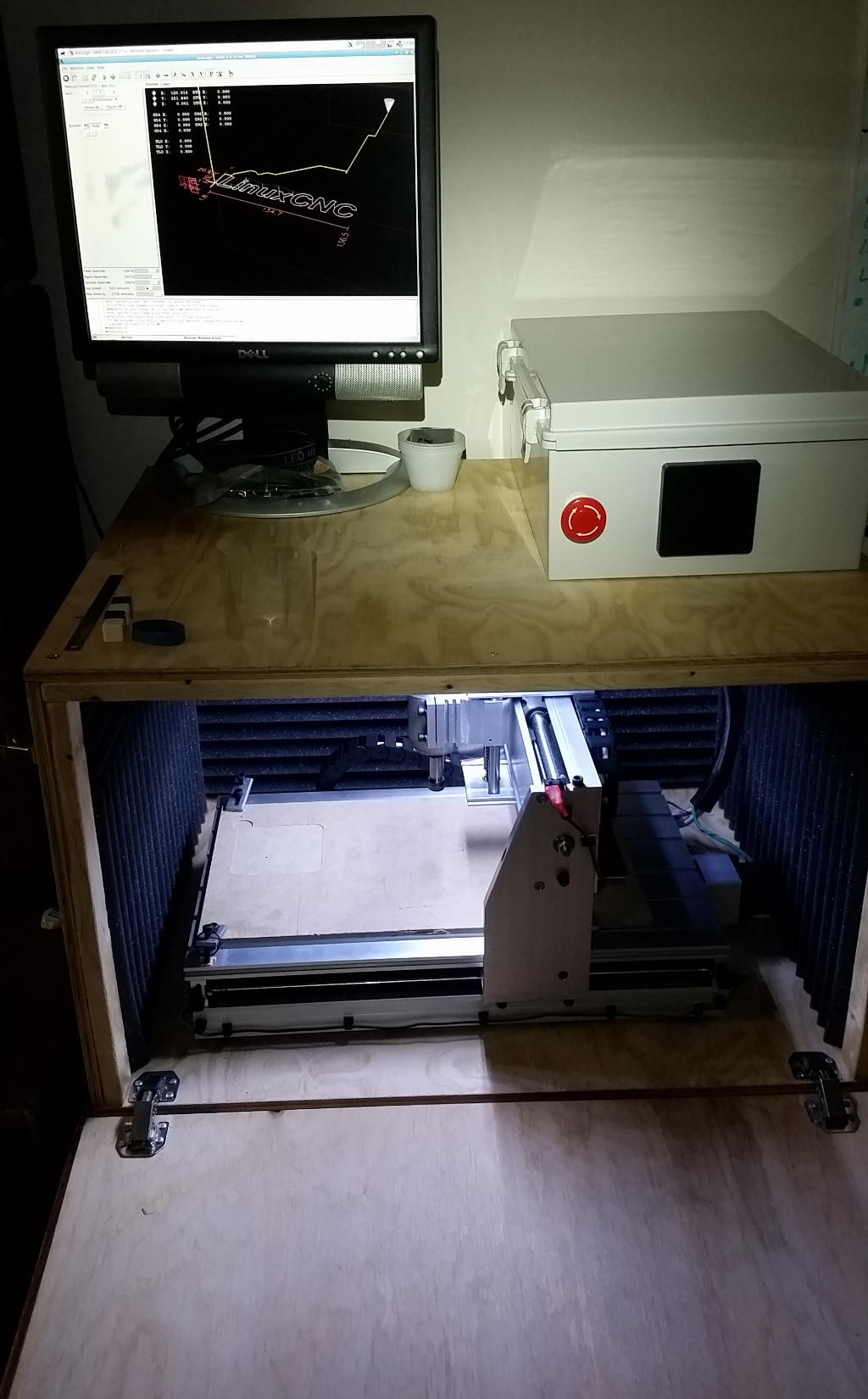
Host and Software
The machine control is being accomplished with LinuxCNC, installed from their Debian spin, running on an old Sempron PC with all the power management features and most of the built-in peripherals disabled to minimize latency. A tarball of my complete LinuxCNC machine configuration is attached for reference, though unless your machine is exactly the same, I wouldn’t run that drop-in. This configuration is good for the particular TB6600 board I have to do unit-correct 3 axis motion, PWM spindle speed (uncalibrated – still need to spring for a non-contact tachometer with enough range), X,Y, and Z combined home and limit switches, E-stop sense, and has sane default rates and soft limits.
Other than the inherent appeal of LinuxCNC, I’m sticking to it because I don’t want a garbage ancient Windows box in my house, which eliminates Mach (and the LinuxCNC feature set is better anyway). Likewise, grbl’s g-code dialect continues to be too feeble for my taste (no functions, variables, or overrides? What?) and the grbl host software is mostly terrible in one way or another. My step rate is a little latency limited, which could be remedied by finding a garbage PC with better latency, or spending money on a Mesa card or something like a Beaglebone and one of the DB25 breakout capes. I would like to see one of the coming generation of ARM SOC based open source motion controllers upset the status quo, but for the moment Smoothieware is the dominant species there, and is still a garbage fire. It would be nice to get the control computer inside the enclosure with the rest of the electronics.
As for design software, I’ve tried a bunch of things. For engraving/carving type work, I still love F-Engrave, even though it is distributed with Windows line endings (^M) in the python that have to be sed’d off every time I decide to update it.
For some other simple tasks I’ve taken to just hand-writing g-code, if I’m just doing surfacing/squaring/pocketing jobs CAD/CAM seems to be more trouble than it’s worth. I’ve heard that some of the conversational/wizard addons for LinuxCNC are really snazzy for that sort of task, but haven’t put much effort into figuring them out yet.
For complex 3D parts, I have to admit Autodesk’s Fusion 360 is the obvious winner. It frustrates me because it really is an excellent workflow, especially compared to other low-end CAD or CAM tools, but it only runs on Windows (GPU demands are such that it doesn’t even do well in a VM) and is “cloud connected” which is generally something I try to avoid. Its path design secret sauce is borderline magical. It also wins because unlike Heeks or FreeCAD, it isn’t completely broken.
Uses
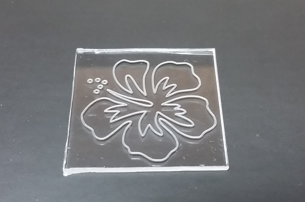
…Hell if I know, I built this thing as a fun project. I’ve done a bunch of engraving, some of which is actually useful. My favorites, not pictured because of personal information, are little brass nameplate ID tags to sew into bags, made out what are supposed to be pipe tag blanks. A noticeable difference from the Shapoko on this kind of task is that the 3040’s repeatability is good enough to re-run a toolpath (for example with a slightly deeper depth of cut) and still get crisp features. The same skills should translate into PCBs; I have the tooling and stock but haven’t had any designs I needed more than one of.
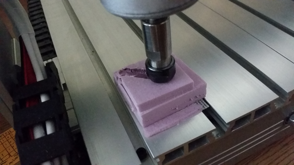
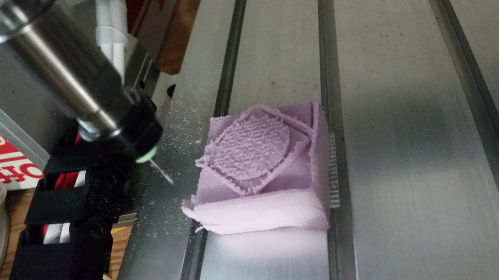
I’ve also done some 3-ish D work in EPS foam just to learn Fusion360 well enough to set that kind of job up. The 72mm Z travel and relatively slow maximum feeds definitely do not suit the machine to large 3D objects, but that does not mean it can’t do complicated 3D toolpaths.
One thing I’m now fully convinced of is the value of simply surfacing a spoil board to establish reference flats. I picked up a cheap 6mm shank, 22mm face bottom cleaning bit, and it is nearly ideal for skimming given the machine size and power. Another little hack I’ve been using is rubber banding a piece of 1L PET bottle around spindle to keep more aggressive bits from throwing the removed material quite so far. I haven’t smacked it into a work piece or anything yet, and I’m pretty convinced it will just tear away and land nearby if I did, since the mass is so low.
I still need to learn to work off a vise (and probably to find a more suitable vise, right now I have a slightly-oversize Harbor Fright drill vise). Almost all my “fixturing” has been strong double-sided tape to surfaced sections of spoil board, which really only works for sheet goods, and there are taller parts to be made. We’ve done some dice blanks on the laser engraver on campus, and I’d like to get in on that.
Some part of me wants to set up a webstore doing [semi-]custom engravings and such just to provide a regular supply of projects.
Closing
The 3040Z really is a satisfying little machine. It’s small enough to be man-portable even enclosed, big enough to make human-scale objects, and stiff enough for arbitrary soft-material work (though I haven’t really pushed it yet). Appropriately enclosed, the noise level and mess is acceptable for use in a living space. So far, it doesn’t seem to require much fiddling to keep it running, unlike the constant tension fights with its predecessor. Like all such machines, its small Z travel and limited power and feed speeds put sharp borders on suitable projects, but I think this machine will cover anything this class of machine might be suitable for.

Hi, great build! What are the external dimensions of your enclosure? I’m in a similar situation, roommates in a house, and am trying to find a good solution that isn’t monstrously large or too noisy. Also, have you done any pcb routing with it? Do you think 0.5mm pin pitch is achievable? Btw, thanks for the great write up.
It’s about 23″ deep, 29″ wide, and 18″ high (the control cabinet sits on top as I have it set up), and makes a nice shelf on the end of the table so it doesn’t blow as much space as it might. That gives enough inner volume that motor housings just brush the tips of the acoustic foam top and back, with a little extra room lengthwise. It’s not silent, but definitely in the range of domestic appliances.
I have copeprclad stock to try (and suitable bits and drills for through holes), but have been too busy to finish a design out to try. I’ve done some solidly fine-pitch engraving so I suspect 0.5mm would be doable with a good setup – you probably would have to either probe or surface off a section of spoil board to get the kid of flatness needed for that to look good, but it wouldn’t be a big deal (and from experience with fine-pitch routed PCBs, would be kind of annoying to solder because of copper height without a solder mask). I think TSOPs would be about the fiddlest package I’d want to do on a routed board.
Fantastic work. And tremendous effort in write-up and documenting. Can I ask if you needed to do anything such as adjustments to the 3040 frame to get the horizontal extruded rods for the bed to be level….. and to be squared up with the moving rail? Also… did you need to do any adjustments to make the spindle column perpendicular to the cutting surface? Once again…. fantastic work.
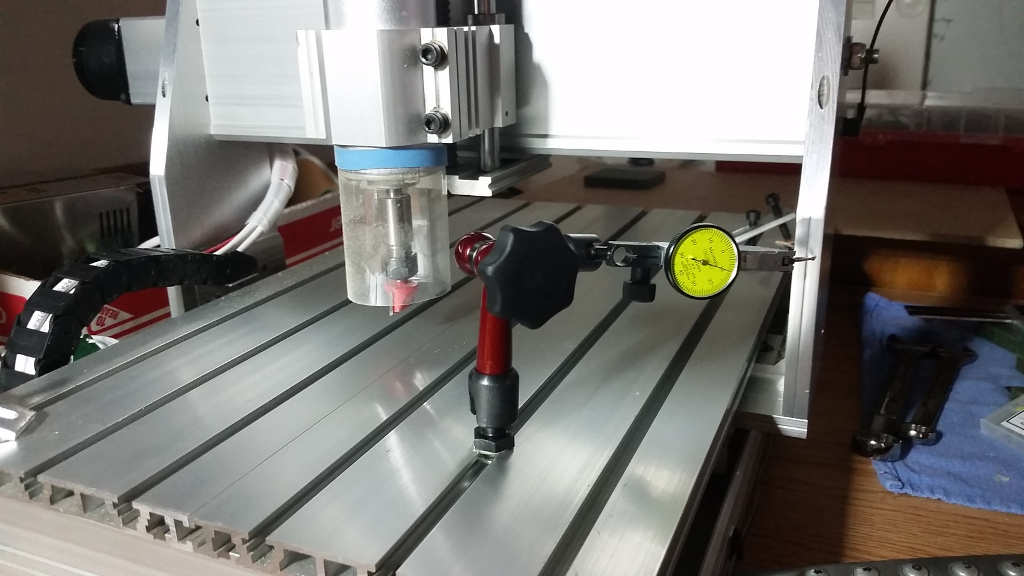
I didn’t have to do much manual tramming and it indicates better than expected. I did the alternating to even torque routine on the bolts and the gantry pulled right in properly – I was skeptical about the little filleted angles and bolt pattern being adequate, but it hasn’t been a problem. Mine is the sort where the Z carriage and spindle mount are a single aluminum extrusion, so there isn’t a lot of potential for tweaking in it, and my gantry came assembled and apparently in-tram.
The only leveling/flatness issue I had with the frame was that I had to pull up the two flat extrusions of the bed, do some deburring to the holes, and put them back down with even torque, as there were some aluminum shavings forcing them out of flat/level as it came.