I’ve done some invasive repairs on the Macintosh LC from my small fleet of vintage computers. I figure it’s worth writing up because there is a lack of detailed information about this kind of work on the ‘net.
I don’t know the full history of this machine, it came into my possession as the result of some horse-trading, but it was clearly a genuine education-market LC, probably manufactured in 1991, and has all the bells and whistles. A perfectly matched 12″ Apple RGB Display (in glorious 512×384 at 256 color with 560×384 mode for the IIe card resolution), the aforementioned Apple IIe PDS card including the often-lost Y-Cable for attaching an (also present) Apple 5.25″ Drive (A9M0107, others won’t work for power supply reasons), all 10MB of RAM the chipset will recognize (2MB soldered in, plus 2x4MB 30-pin 100ns SIMMs), a 40MB Connor Hard Drive, and one of the good SuperDrive type internal floppy drives. All blazing along at 16Mhz with no MMU or FPU and a 16-Bit bus. The system is an excellent candidate for a retr0bright job, the plastics are not showing any signs of embrittlement, but are extremely bromine yellowed; it’s somewhere way down on my project list. One lovely thing about LCs is there are no assembly screws; every major component clips in to a delightfully compact case, so it’s unusually pleasant even by modern standards to work on. Unfortunately, some years ago, it died, and I didn’t want to let it go.
Like the vast majority of my interesting retro hardware, my LC is stored in my parent’s house, where I usually only spend time when I’m tending it because they’re travelling, and I’ve had to order parts between steps, so this has been over a year in the doing.
Power Supply
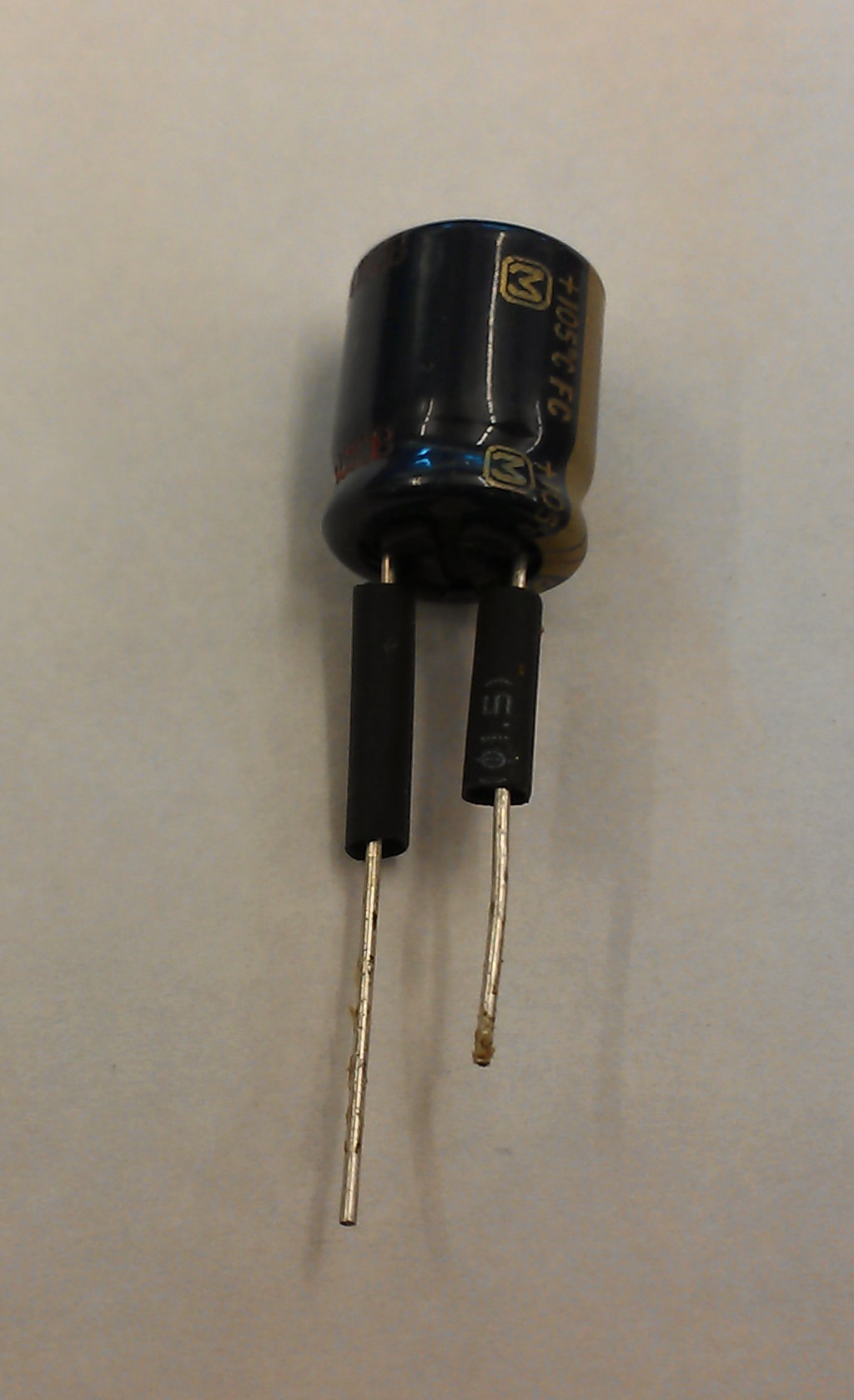
I strongly suspected the problem was in the power supply, and some time back I read up on failure modes and listened for the telltale clicking to verify. The excellent MacCaps reference for these power supplies indicates that there are some 56μF and 270μF ELNA Long-Life caps that tend to be decidedly not long-lived, particularly in the TDK-manufactured supplies (which mine is), so I chose that as a first fix.
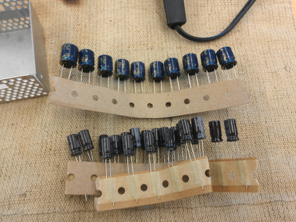
I dug around the ‘net for a good source of replacement caps, and eventually found an ebay seller who apparently specializes in audio electronics with nice low-ESR capacitors from reputable brands with the right values and working voltages at least equal to the ones installed. I ended up in particular with this 56μF and this 270μF model. which then sat in my apartment for months until I got around to installing them. The Ratshack firestarter visible in the corner of the picture is the extra iron we keep in the lab for jobs that we know will permanently contaminate the tip – it’s mostly used for plastic welding, but is also great for shoving into pools of mostly-dried 90’s vintage capacitor electrolyte.
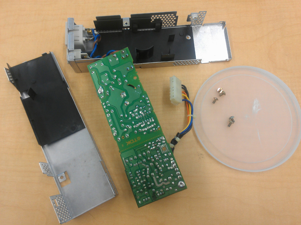
I dragged the PSU into the lab (Where my personal soldering equipment often ends up due to other people’s problems), removed the old caps, did my best to clean out the old leaked electrolyte with swabs and isopropanol, and put in the replacements.
The 25V 270μF are naturally a bit bigger than the original 10v, which required a bit of creative installation – I ended up just putting bits of heat-shrink on the legs and mounting it above where it was supposed to go.
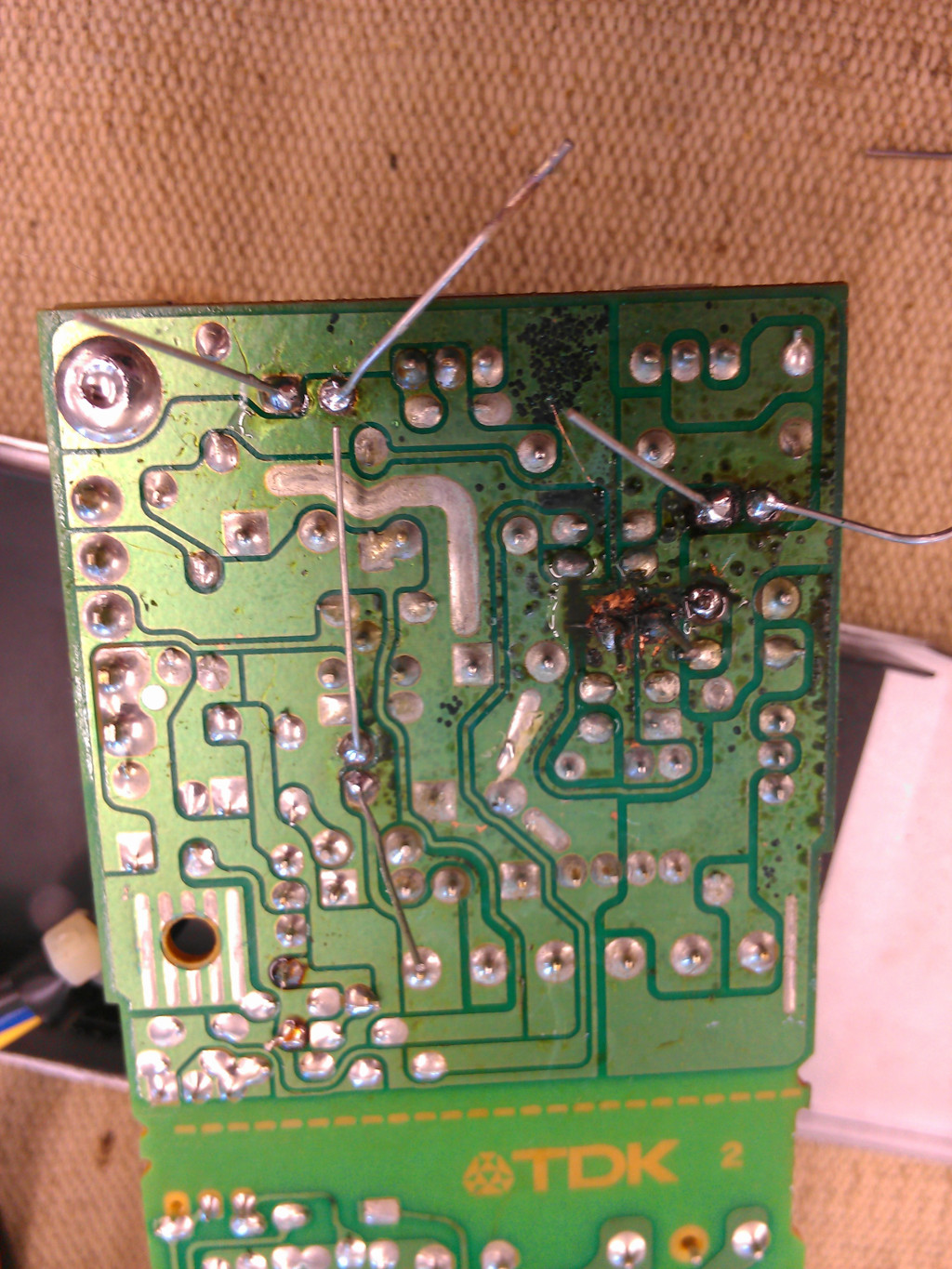
After that…it was still making the reset clicking, and while the +5V and +12V rails read spot-on, the -5V rail was reading about -3.5v and unstable. So, I swapped the Nichicon 1000μF caps on the low-side with pulls off a motherboard in the lab junk pile. One of the 1000μF caps I replaced did have some electrolyte residue under it, but I think it was spew from elsewhere, in retrospect I’m fairly certain they were all fine. There is also some rather ugly damage to the PCB from the leaked electrolyte.
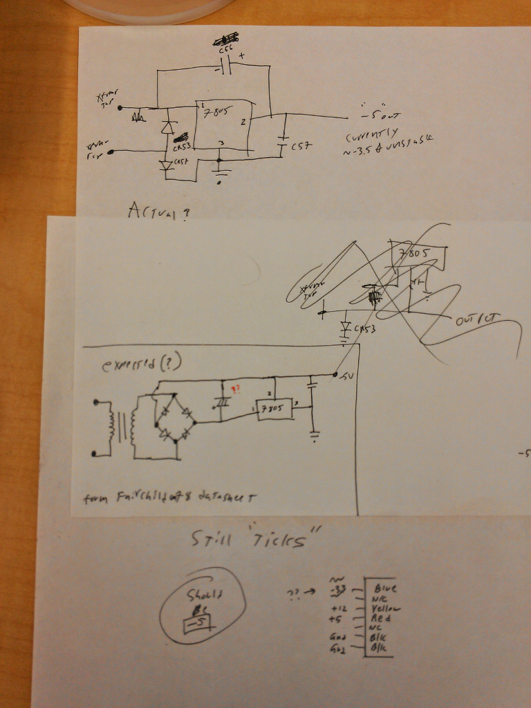
I then got desperate and reverse-engineered the -5V supply circuit, which turns out to just be a cheap implementation of the negative-voltage supply from the Fairchild 78xx data sheet application notes (see Fig. 17).
Verifying that there was nothing that could be wrong with the circuit, I realized I was an idiot trying to test a PSU with no load on it, slapped it back in the machine because that was easier than sticking dummy loads on all the rails (In case of sense lines or the like), and it powered right up and read stable on all rails.
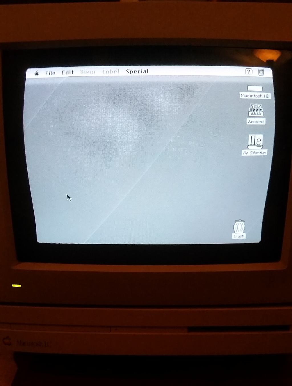
The fan spun up, the ancient Conner hard drive spun up and did a proper-sounding sync routine, but I didn’t get video output or a chime of any sort. Then, I realized I was still idiot. I pulled the PRAM battery to avoid leakage before I packed it up last time, and LCs are well known not to boot without a live PRAM battery. I seem to have thrown out all my suspect old 1/2AA 3.6V cells, so another delay later, new batteries in hand (Amazon was cheaper than the various Chinese export vendors for these), the LC made its happy chime and booted right up… but the lone ADB port is dead.
Motherboard
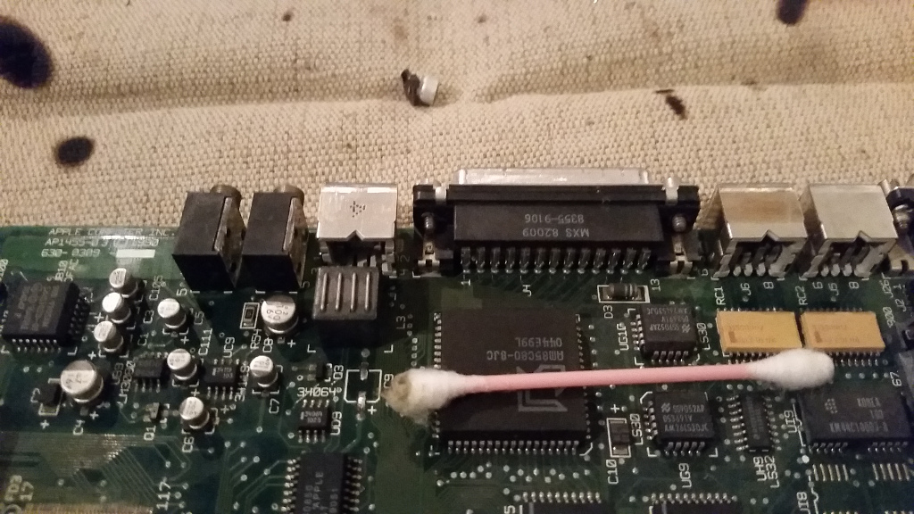
The ADB problem lead to a board inspection, which lead to some evidence of leakage in an SMT electrolytic behind the ADB port, which lead back to maccaps.
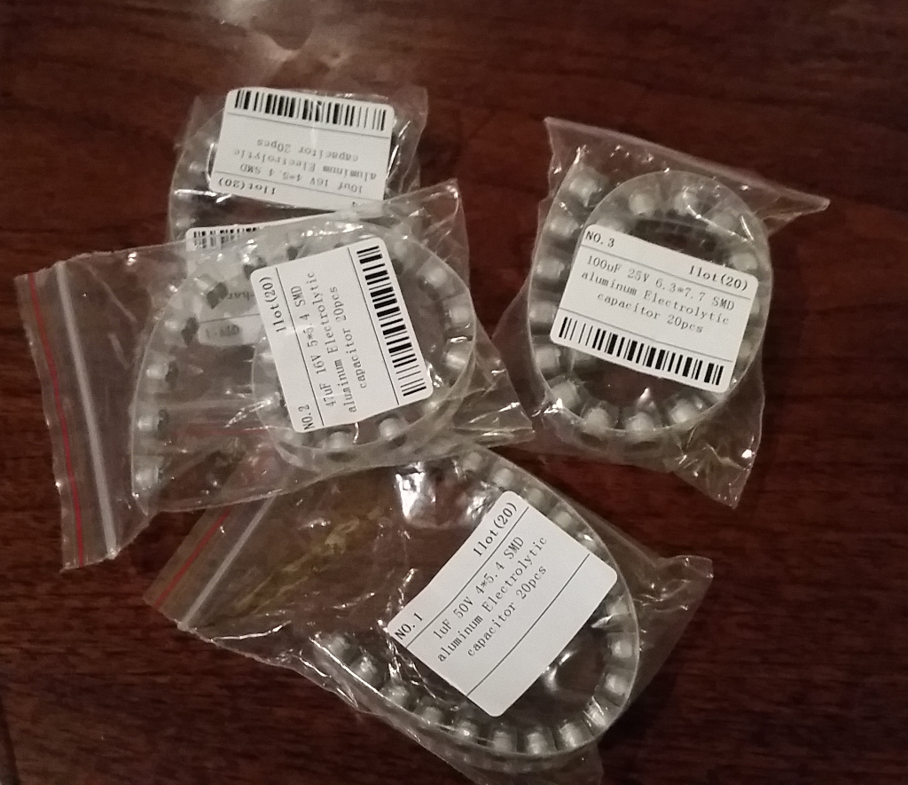
This time the WeMos Electronic Aliexpress storefront came through with my parts. I played it safe and bought replacements for every electrolytic on the board, which came out to less than $10 total – 20pc cut-tape strips of 47uF 16V 5*5.4 SMD aluminum Electrolytic capacitors (these are actually one size too small), 1uF 50V 4*5.4 SMD aluminum Electrolytic capacitors, 100uF 25V 6.3*7.7 SMD aluminum Electrolytic capacitors, 10uf 16V 4*5.4 SMD aluminum Electrolytic capacitors – I’d recommend them but they don’t seem to do open-stock SMT capacitors anymore.
The most suspect caps were the pair of 47uF caps – one was visibly leaking, and the other was the cap closest to the ADB circuitry, so I decided to start with them. Some people advise crushing the can off of SMT caps with dykes to make them easier to remove, but I much prefer just desoldering pins on either side from the edges while gently lifting with tweezers, then cleaning the affected area with an alcohol swab to remove whatever taint the dead cap left behind.
Re-tin the pads, pop the new part in, heating from the edges. Remember that the dark band goes toward the negative side; they will explode if installed backwards. The motherboard silkscreen helpfully has the positives marked for most of the caps.
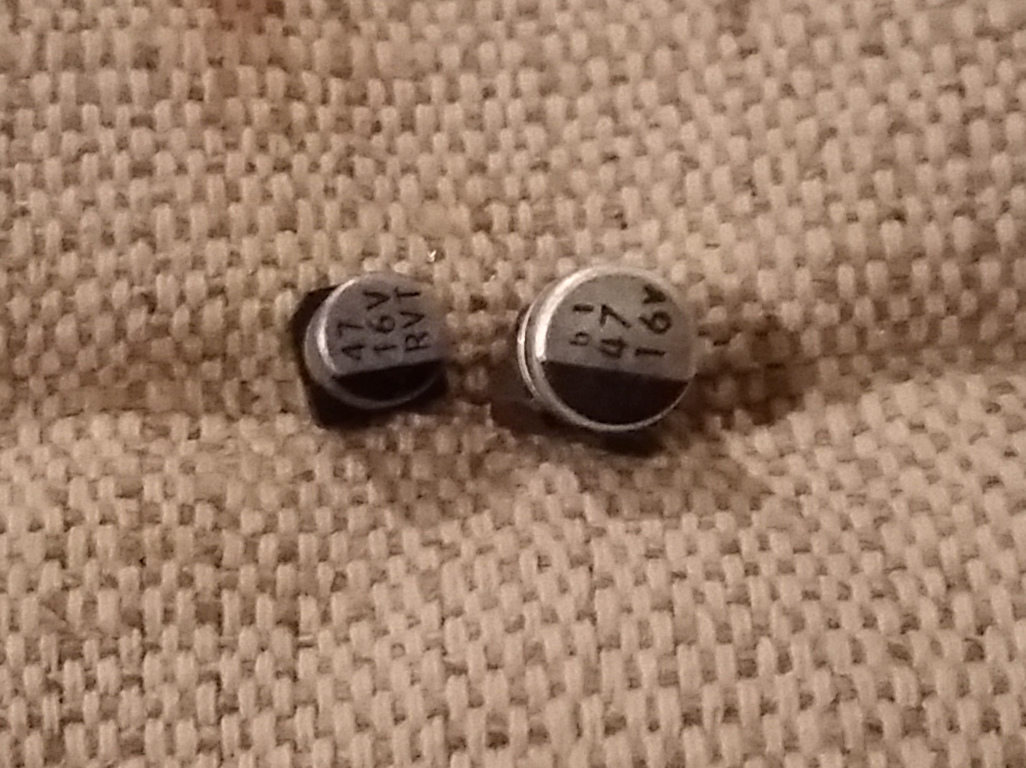
My 47uF replacements appear to be one size too small – the new ones are 5.5×5.5 I think the originals were 6.3×5.5 – this actually makes the swap easier because it gives more exposed pad to edge-heat, and more maneuvering room on and around the footprint.
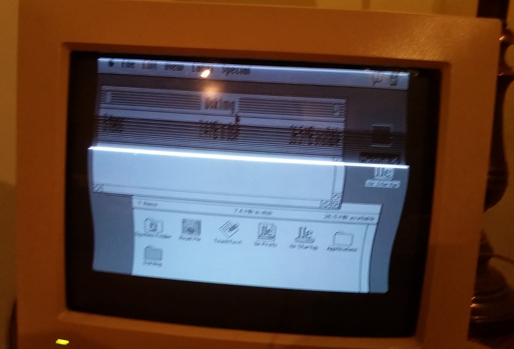
To avoid putting unnecessary stress on the motherboard, I decided to check after the obvious problem was fixed, and sure enough, the ADB devices were now working. Unfortunately, the video was horribly distorted, and I thought I might have cooked the video output on the LC. The distortion went away when I hooked up my remaining good standard Apple Color Display, so it must be in the 12″ RGB Display, and the other LC motherboard caps join my parts bins. The 12″ display gets better up to the level of “slightly pear-shaped” after a warm-up period, which makes me suspect marginal caps on the deflection board, but I’m always reluctant to mess with CRTs so I’m putting that off for the time being.
Victory, some pining for the days when it was practical to repair consumer electronics, and a reminder that almost all electronic problems can be traced to defunct electrolytic caps.

Did you remove the rotten soldermask? (Black splotchy). I usually scrape it off then tin the exposed copper and lawyer it to prevent normal air rust.
Also, I’d not trust caps from random Chinese sellers, especially using the same kind of can caps that already leaked. Generally all the Mac recappers switch to tantalums…
Lawyer=laquer
I left the damaged soldermask intact on the PSU, I’m afraid the substrate is compromised and didn’t want to do any more damage trying to repair it. It may eventually finish dying, but for now it seems OK. The caps I got for the PSU are (apparent) name-brand low ESR offerings, and the ESR checked out on a meter, so I’m as certain as one can ever be that they’re genuine.
The caps I bought for the Motherboard are in fact Chinese nonames, I’ve never observed much brand differentiation among that kind (Possibly because they are rarely marked and difficult to trace). I didn’t even think to look for compatible Tantalums, despite their longer life and lower failure odds, I worry about Tantalum sourcing ethics, and also matching – I’m pretty sure I could have done legit spec-for-spec swaps for this one, it’s not a bad idea for future projects.
I fixed a 12″ RGB monitor with this exact issue. it IS a leaky cap, its right near the yoke connector. it spills over on the yoke.
Also, if you leave the monitor on long enough it will fry the horizontal output transistor, it did mine. I have a youtube channel troubleshooting this monitor, and I still have a ton of footage of the actual repair I still need to upload.
Cool, thanks for the pointer.
I have a problem with my mac lc, the capacitor C13 (near the power supply) is brocken.
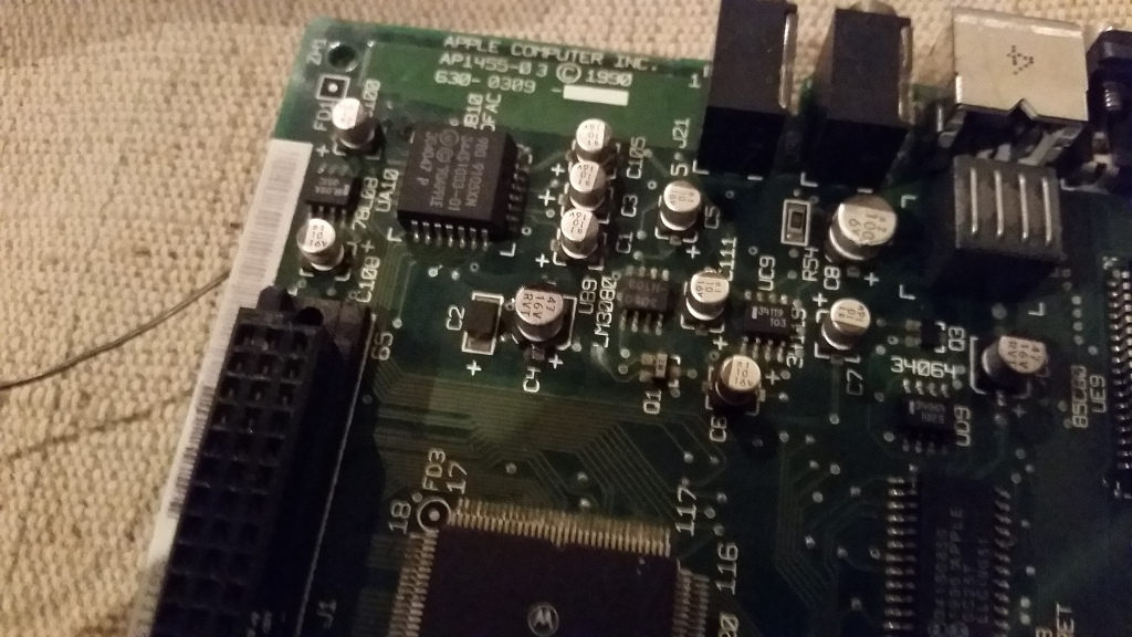
I would be glad if you could post a picture of the full mainboard so I could see what capacitor is broken, and what i have to get for replacement.
Sorry for taking forever to get back to you on this, my LC doesn’t live with me.
Here is a full motherboard picture and a detail of the C13/C14 area, the caps in question are 47uF/16V.
Better than that, the Maccaps reference for the LC has not just a full picture, but a full picture with annotations.