Source: Ken Shirriff's blog
Article note: I went on a reading binge about the Philco and DEC (eg. https://hackaday.io/project/8449-hackaday-ttlers/log/130460-bizarre-dtl-logic-levels-the-discrete-component-pdp-8, mostly using Philco surface-barrier transistors) early transistorized machines the other day, and they are "weird."
I didn't realize the 1401 was "IBM Weird" with this "We made several different kinds of DTL gate, some with PNP and one with NPN, you have to alternate them so the voltage levels work, they take different supplies, and there are 21 different options for those voltages" business. Plus some gates with pullups and some without to rig wired-OR, and all the other batshit "we're going to shave a transistor by any means necessary because it's 1959" antics Ken gets in to here.
How did computers implement logic gates in the 1950s?
Computers were moving into the transistor age, but transistors were expensive so circuits were optimized to minimize the transistor count.
At the time, they didn't even use silicon transistors; germanium transistors were used instead.
In this blog post, I'll describe one way that logic gates were implemented back then: diode-transistor logic.

The IBM 1401 computer, showing some of the cards inside. (Click any image for a larger version.)
The IBM 1401 computer, above, was introduced in 1959 and became the most popular computer of the early 1960s, with more than 10,000 in
operation.
It was constructed from thousands of circuit cards, each implementing a function such as a few logic gates.
The logic gates in the IBM 1401 use (for the most part) a simple form of logic called
CTDL (Complemented Transistor Diode Logic) by IBM and DTL (Diode-Transistor Logic) by the rest of the world.
As the names suggested, these gates are built from diodes in conjunction with a transistor.1
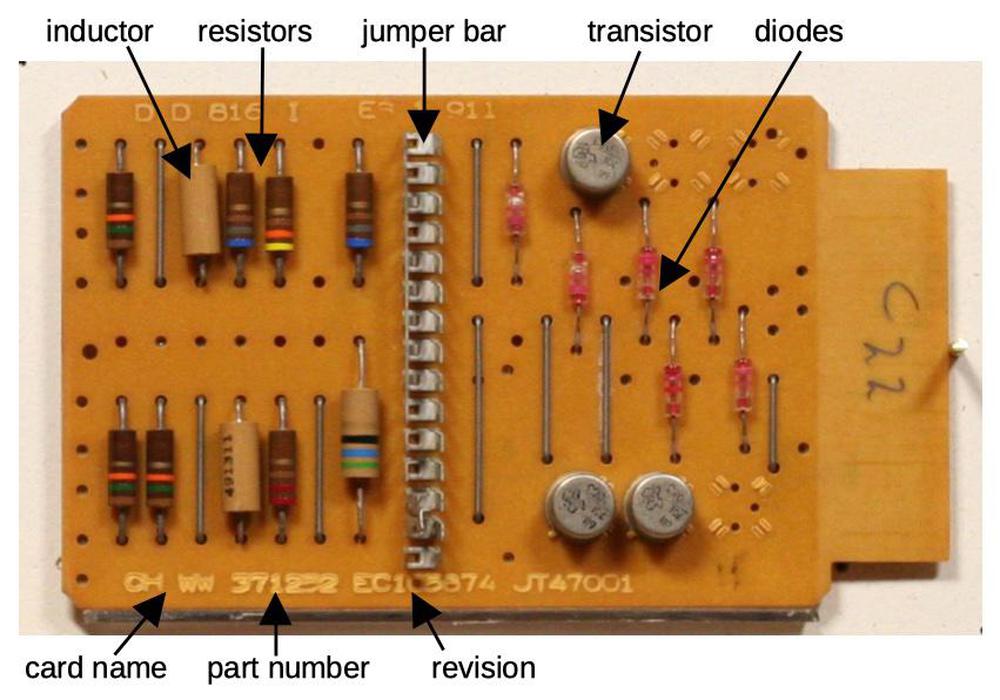
This SMS card (type CHWW) implements three NAND gates so there are three transistors.
These cards are about the size of a playing card and called SMS cards, Standard Modular System.32
Each type of card has a code, typically four letters. The card above is a "CHWW" card, implementing three NAND gates.
It contains a handful of components: transistors, diodes, resistors, and inductors.
One unusual component is the jumper bar in the middle, called a "program cap".
Breaking off tabs from this bar allowed the functionality of the card to be changed slightly so one card could fill multiple roles.
The back of the card (below) shows the traces of the printed circuit board as well as the connector with 16 gold-plated contacts.
More details of the CHWW card are in my SMS card database.
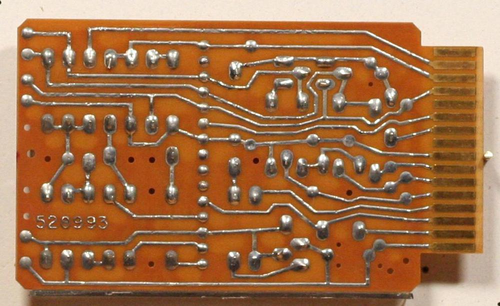
The back of the card has the PCB traces and the gold-plated edge connector.
Logic circuit implementation
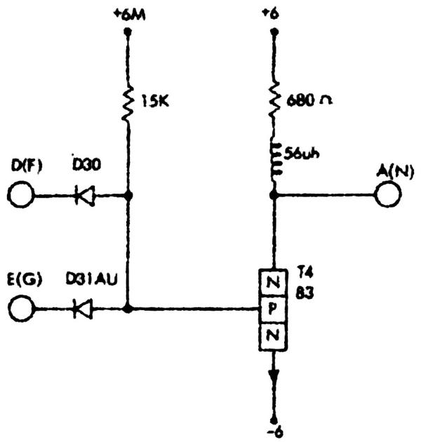
The CHWW card contains three NAND gates. The schematic below, from IBM's 1959 documentation, shows one of these gates.
Note IBM's unusual symbol for a transistor, showing the N-P-N structure explicitly, with an external arrow for the emitter.
I've redrawn the schematic below using modern symbols.
The arrows show (qualitatively) what happens when the gate has two high inputs.
The left arrow indicates the current through the resistor and the transistor's base.
This base current turns the transistor on, connecting the output to -6 volts, and producing a low output.
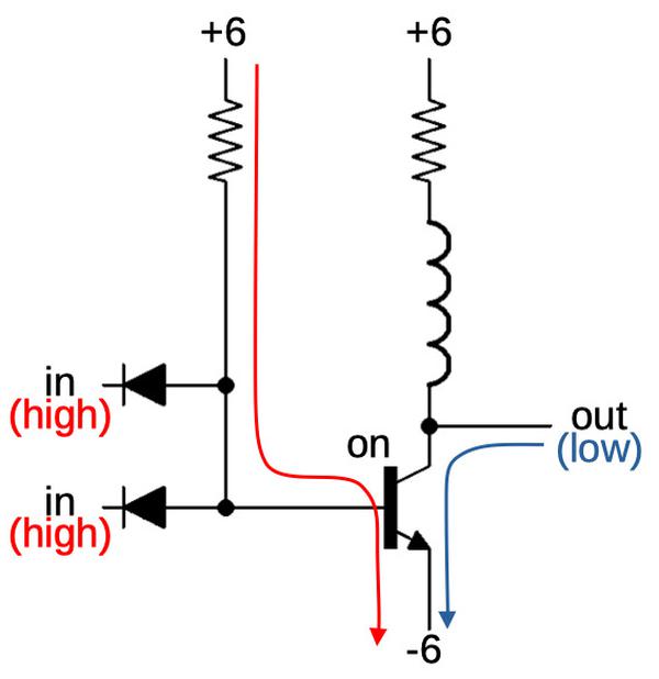
If both inputs are high, the output of the gate is low.
If there are one (or two) low inputs, however, the resistor's current flows out through the diode, rather than through the transistor.
With the transistor off, the output is pulled high by the pull-up resistor.
The result is a NAND gate: the output is low only if both inputs are high.
In this circuit, the diodes are the components that compute the logic function.4
The transistor amplifies (and inverts) the result.5
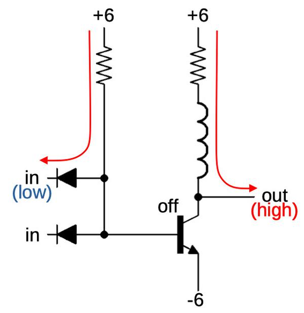
If an input is low, the output of the gate is high.
There's a problem with this gate though. The output voltages are approximately +6 volts for a high signal and -6 volts for a low signal.
You'd like the gate to switch when an input is roughly in the middle of this range.
Unfortunately, the transistor in this circuit will switch when the input is around -6 volts. Thus, the input voltage and output
voltage levels are incompatible and you can't connect two gates together.
There are several solutions to this problem.
The first solution is to use additional diodes and transistors to shift the voltage levels to be compatible.
Fairchild used this approach in their popular Micrologic line of DTL integrated circuits in the 1960s.9
The second solution (used in IBM's SDTDL circuits) is to shift the voltage levels by using additional resistors.
The 1401's gates, instead, uses a surprising solution that avoided extra components.
In the gate above, the output voltage levels are raised up compared to the input.
But a similar gate with PNP transistors instead of NPN transistors will have the opposite property: the output levels will be lowered.
So IBM's solution was to alternate gates built with NPN transistors with gates built with PNP transistors.
The first gate raises the voltage level up, and the second gate lowers it back down.
You have twice as many types of gates, and it's more complex to design, but you avoid the expense of additional components.
The photo below shows the PNP-based NAND gate card.
It is almost identical to the previous NPN card, except the transistors are PNP instead of NPN.
The other difference is that it is powered with -12V and 0V instead of -6V and 6V.6
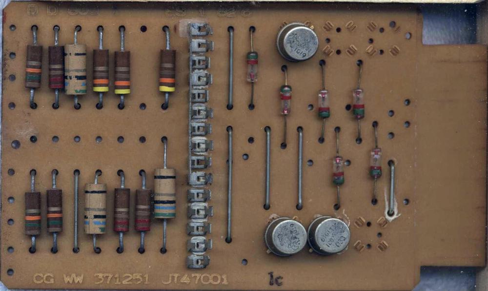
The CGWW NAND card is built with PNP transistors.
In more detail, for the NPN gate we first examined, the input switches around -6 volts, and the output is about -6 volts or 6 volts.
In the corresponding PNP gate, the input switches around 0 volts, and the output is -12 volts or 0 volts.
IBM called the -6V/6V levels type "T" and the 0V/12V levels type "U", so an NPN gate has a U input and a T output, while a PNP
gate has a T input and a U output.7
By alternating NPN gates and PNP gates, you have T outputs going to T inputs and U outputs going to U inputs, and everything works.8
The diagram below shows part of the logic diagram from the 1401's adder, heavily simplified.
Two type U signals go into the first CHWW gate, which outputs a T signal. The 4JMX gate
is a PNP NAND gate that takes T inputs and outputs a U.
The CRZV is an NPN buffer that converts U to T.
Finally, CNWT is an NPN driver that amplifies a T signal, in this case a binary carry-out signal.
Note how the signals alternate between T and U (except for the last special driver).

Wired-OR
There's one more interesting trick with these logic gates: wired-OR.
The idea is that you can wire the outputs of several NAND gates together. If any gate outputs a logical 0, that gate will pull the output low.
If all gates output a logical 1, the output will be pulled high by the pull-up resistor.
The resulting circuit implements an AND-OR-Invert gate.
The diagram below illustrates how the NAND gates are wired together and how the circuit behaves logically.
Wired-OR circuits are widely used in the 1401 because you get the OR gate "for free", minimizing circuitry.
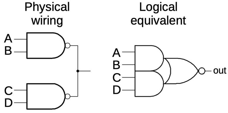
An AND-OR-Invert gate. This shows two NAND gates but more can be connected.
There's one minor issue with wired-OR: if you wire standard NAND gates together, you end up with multiple pull-up resistors in
parallel, which will affect the gate behavior.
The solution is to use gates without pull-up resistors, except for one gate that has the pull-up resistor.
For example, the 4JMX card has the pull-up resistor (called a "collector load"),
while the 3JMX card lacks it.
Thus, a wired-OR could use one 4JMX card and the rest would be 3JMX.
(This is one reason why there are so many different types of SMS cards.)
Since each card only implements a small amount of logic, the IBM 1401 computer requires thousands of cards. The photo below shows how they are mounted inside the computer.
I won't go into more detail here about how SMS cards are combined to create functional units,
but I've written about the circuitry in the 1401's adder if you want to learn more.

SMS cards installed in the IBM 1401 computer. The fan at the left keeps the cards cool.
The transistors
These gates use bipolar NPN and PNP transistors, types of transistors that are still used today.
But the germanium
alloy-junction transistors
were completely different from modern silicon planar transistors.
The photo below shows the construction of an NPN alloy transistor,
It consists of a P-type germanium crystal base with tin/antimony beads fused on either side to form the emitter and collector.
The regions of germanium-antimony alloy form the "N" regions. The resulting N-P-N layers form the NPN transistor.
(A PNP transistor is formed similarly, using indium for the alloy.)10
In the photo, the vertical metal plate is the base contact with the tiny germanium disk in the circular hole. Copper wires are connected to the indium beads on either side of the germanium disk.
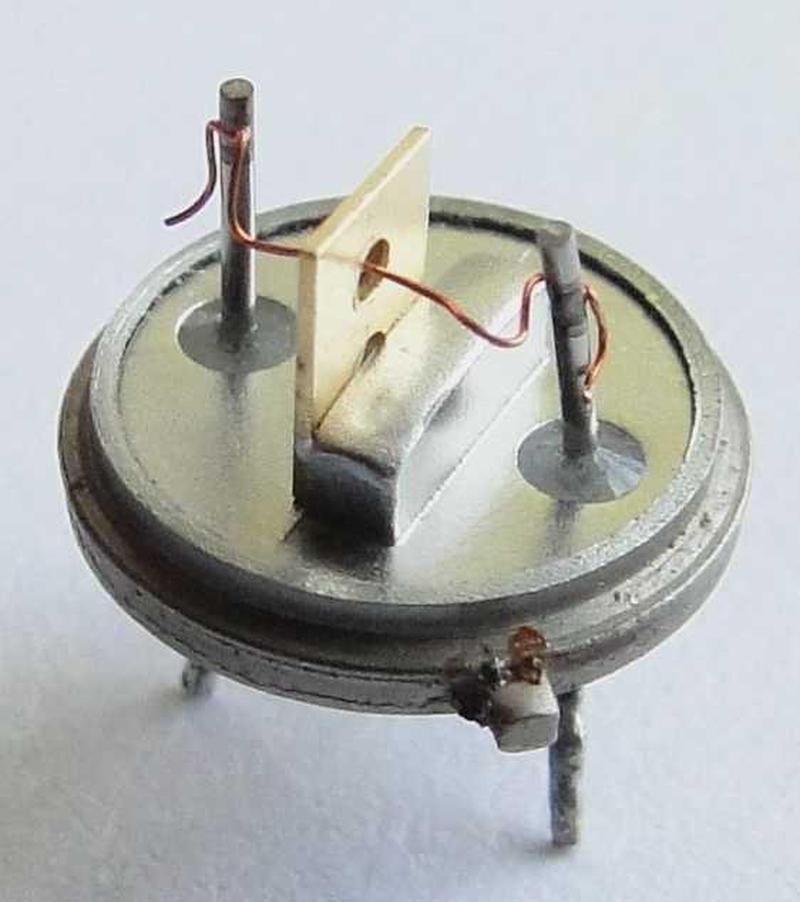
The 1950s were a time of rapid change in transistor technology.
The transistor was invented at Bell Labs in 1947.
General Electric invented the alloy junction transistor (used in the 1401) in 1950.
In 1953, the drift transistor was created, faster because of its doping gradient.
IBM used drift transistors in the Saturated Drift Transistor Diode Logic (SDTDL) family.
The first silicon transistors were introduced in 1954.
The wafer-based mesa transistor was invented in 1958, followed by the
modern planar transistor in 1959.
Thus, transistors were undergoing radical changes in the 1950s and
IBM introduced new logic families to take advantage of these new transistor types.
Conclusion
Diode-transistor logic was a key part of IBM's early computers such as the IBM 1401.
In 1964, IBM introduced the groundbreaking System/360 line of mainframes.
These computers still used diode-transistor logic, but instead of SMS cards with discrete components, the logic was encapsulated in small SLT modules (below)
that contained tiny silicon transistors and diodes.
An SLT module was roughly equivalent to an SMS card but just half an inch on a side and almost 100 times as reliable.
The density, low cost, and reliability of SLT modules were important to the success of the System/360 line.
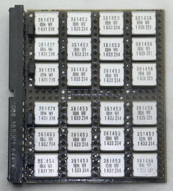
A board with 24 SLT modules on it, probably from the System/360. The
361453 modules implement AND-OR-Invert.
In the 1960s, diode-transistor logic integrated circuits were introduced.
But DTL was soon eclipsed by the rise of TTL (transistor-transistor logic) in the late 1960s.
In the 1970s, integrated circuits with MOS transistor logic became common, especially for microprocessors.
CMOS logic took over in the 1980s and it's still the most popular logic family.
Thanks to Moore's Law,
technology has progressed from the IBM 1401 era with a few transistors on a board to modern microprocessors with billions of transistors on a chip.
The Computer History Museum in Mountain View, CA has two working 1401 computers, so stop by for
a demo (once the pandemic is over).
Thanks to bogomipz for suggesting this topic.
Thanks to Randall Neff and Henk Stegeman for SMS card photos.
I announce my latest blog posts on Twitter, so follow me @kenshirriff. I also have an RSS feed.
Notes and references
-
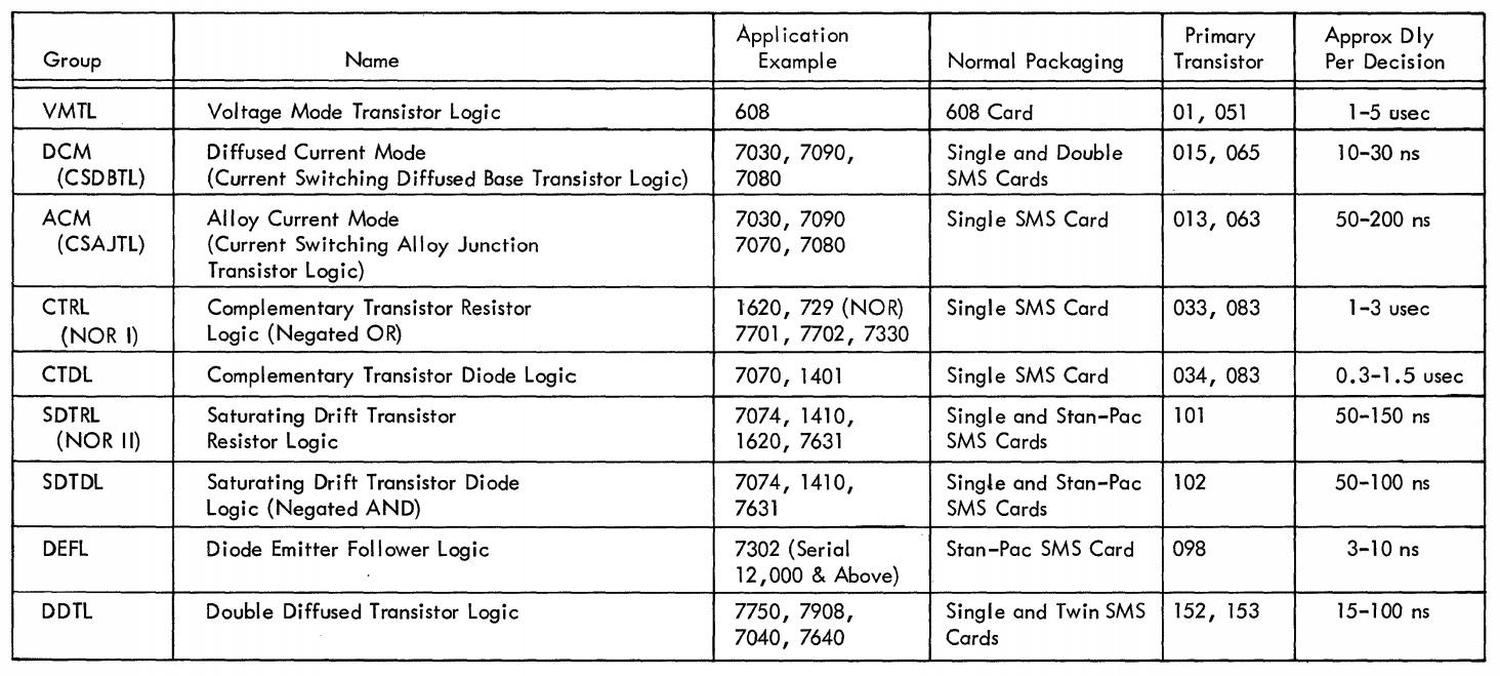
IBM used a dizzying assortment of logic families in that era.
Even the 1401 used multiple families (mostly the CTDL discussed above but also current-mode and STDTL in the TAU tape controller, and occasional SDTRL).
The table below from 1963 summarizes IBM's numerous logic families.
CTRL (Complemented Transistor Resistor Logic) used alloy-junction transistors. It was slow, operating below
200 kilohertz.
CTDL (Complemented Transistor Diode Logic) also used alloy-junction transistors but operated up to 250 kilohertz.
(The Complemented families alternate NPN and PNP circuits.)
Current mode (similar to emitter-coupled logic) was much faster as transistors weren't saturated and the voltage swings were small
(±.4V). It operated at 1 megahertz with alloy-junction transistors, and 7 megahertz with diffused junction transistors.
For more discussion, see
Transistor Component Circuits and
Logic families in the 1401.
There's an interesting discussion in Wikipedia's DTL talk page by William Crouse, who designed many of the SDTDL circuits at IBM. ↩
-
IBM also offered SMS cards as components for other companies to use in products.
The announcement below is from Datamation in 1966.
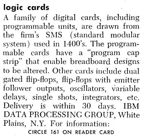
A product announcement for SMS cards from
Datamation, 1966.
↩
-
The idea behind Standard Module System cards was that IBM could manufacture a small number of standardized cards and build systems from them.
Unfortunately, standardization worked better in theory than in practice and IBM ended up with thousands of different card types.
As well as logic functions, SMS cards had a wide variety of roles including oscillators, printer drivers, core memory arrays, sense amplifiers,
power supply regulation, and tape preamps. ↩
-
Many vacuum tube computers used semiconductor diodes as a key part of their logic gates.
I think that diodes don't get the recognition they deserve; computer generations are divided into tube versus transistor, without
recognizing the gradual introduction of semiconductors in the form of diodes. ↩
-
Note the inductor connected to the output of the gate. The inductor increases the speed when pulling the output high.
The problem is that the output is pulled high through a resistor, so any capacitance on the output wire results in a delay as it is charged.
The inductor counteracts this capacitance. To handwave, once the resistor starts pulling the signal up, the inductor keeps the current
flowing.
More discussion of the peaking coil here. ↩
-
Here's the schematic of the PNP-based NAND gate used in the CGWW card.
It is similar to the NPN-based gate, except the circuit is flipped and runs off -12 volts.

↩
-
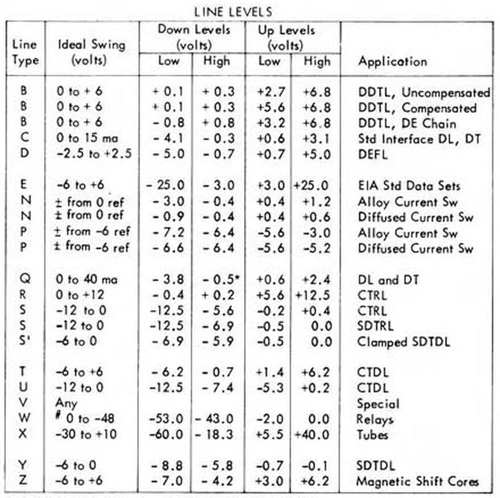
IBM used a remarkable number of different voltage levels for its logic families.
The CTDL gates described in this article used the "T" and "U" levels. The table below gives the others.
↩
-
I should point out that having two sets of voltage levels makes debugging the 1401 system very confusing.
If you measure -3 volts, for instance, this is a logical low for a T signal and a logical high for a U signal.
The wired-OR gates also make debugging inconvenient. If the output is low, you can't easily tell which NAND gate is pulling the output low, and these
NAND gates may be on different cards with many different inputs. ↩
-
The schematic below shows the implementation of a NAND gate in the Fairchild Micrologic family of integrated circuits.
This circuit uses an additional transistor and diode to shift the voltage levels.
This was practical in an integrated circuit because the additional components had minimal cost.
This circuit wouldn't have worked well in the IBM 1401 because the 1401's germanium components provided a much smaller
voltage shift than the silicon components in the Fairchild IC.
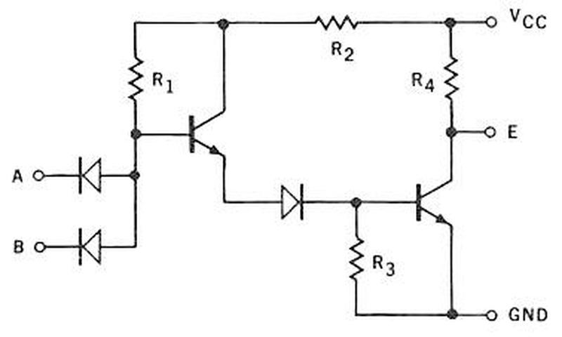
Schematic of a Fairchild Micrologic DTL gate from the
databook.
↩
-
The periodic table shows why elements such as indium were used in the alloy transistors. Note that the semiconductor germanium is in the same column as silicon, which later replaced it.
Indium and gallium are in the column to the left, so they have one fewer valence electron. Thus, adding them to the semiconductor makes it more positive (P-type), since electrons are negative.
Antimony is to the right; its additional valence electron makes the semiconductor negative (N-type).
Tin, in the same column as germanium, was used in the alloy but has no effect on the semiconductor properties.
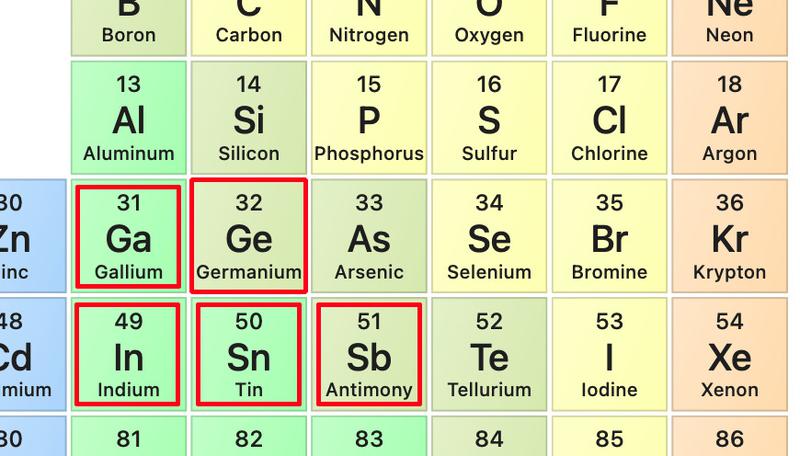
This excerpt of the periodic table shows key elements in transistor construction. Source:
NCBI.
↩


