I’ve been in a very mechanical sort of mood for the last couple days, no doubt owing to the all-software (and intangible even for that – what does that thing you’ve been working on do? – well, if I were sure it was working it would verify that an input sequence is valid in this language I made up…) sorts of things I’ve been doing of late. So, I pulled out my pile of mechatronics parts and started fiddling with it.
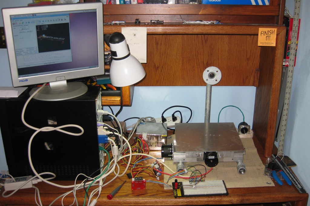
I’ve previously documented some of this elsewhere, and this isn’t a finished project, but I need a brain dump to package up various information, so I’m going to do a fairly thorough write up.
Mechanical:
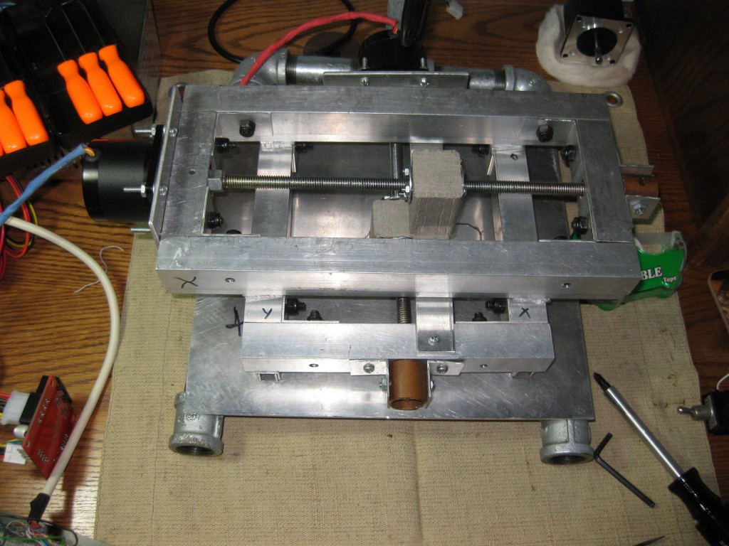
I have a simple aluminum XY table built starting about two years ago, with (in principle) about 9″ of X travel and 6″of Y travel. The table was largely an inexpensive project in learning to work with metal and linear motion parts, partly written off in time and money as a project for a controls class (which is to say, it’s sloppy and full of mistakes, some of which will be documented below). As a result, is only a ~$100 parts investment, and I’ve learned more from it than most $100 textbooks I’ve owned. It is mostly built from 6063 aluminum – framed in 1″ square tubing, with a lot of parts made from 1/4″ thick plate. The slides are also aluminum – each one is made from nested aluminum U-channel, the outer piece intended for edging 1/2″ plywood, and the inner piece for edging 3/8″ plywood. Part of the genesis of the design was the observation that those sizes of inexpensive easily available channel nest snugly and slide easily when oiled. I really like working in aluminum – the easily available stuff is less flexible than comparable ferrous materials, doesn’t spark when cut, and soft enough to be easily worked. The lead screws are made of 3/8-16 UNC threaded rod, which sucks as a lead screw, but is enormously cheaper to work with and easier to source than any or the more suitable thread forms. After several miserable failures, the current drive nuts are assembled from pieces of Trex and Tee-nuts, documented here. The leadscrews are coupled to the motor output shafts by center drilling a 1/4″ hole into the end of the shaft, and running a set screw through a 1″ coupling nut sized (by flowing solder into the threads) around the end of the shaft.
The table is resting in a simple 3/4″ iron pipe frame, to which I haven’t quite figured out how to attach it permanently (requires leveling adjustments and such). Currently, the “Z axis” is a ruler with a sharpie taped to it, twist-tied to the frame, so that I can easily trace out XY motion.
Electromechanical:
Motive force comes from NEMA23 stepper motors driven by microstepping drivers.
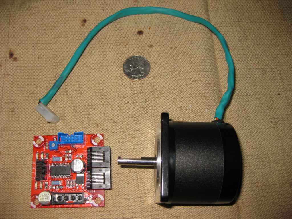
The motors are Lin Engineering 5618S-58-01, which I picked up for about $12 each from alltronics a few years ago – the exact model number doesn’t appear on Lin’s website, and they were advertised as overruns on a custom order, which explains why they were so cheap. They showed up in good condition and came with adequate data sheets, so being oddballs isn’t a disadvantage. Specs-wise, they are four-wire bipolar windings, produce about 130 oz-in of holding torque (about 1Nm, for those using saner units), move 1.8°/step (200 steps/rev), and max out at 2A per phase. I would probably try for something in the 250 oz/in range for a more serious project, but these have worked well so far, and are easy to handle (less potential for finger breaking and fire starting than their more powerful brethren), so they’re nice for learning.
The drivers are RepRap/MakerBot Stepper Motor Driver v2.3 boards, which I picked up as kits for about $16/ea from MakerBot Industries — they don’t seem to offer them anymore, which is a shame, because they cost less than half as much as anything else I’ve seen that can drive 2A, including their $40/ea immediate replacements. I’m not all that fond of the board layout and choice of connectors, but the Allegro A3928 chips the boards are based on are pretty awesome and apparently rather difficult to design around. There was also a problem with assembly, but after a couple rounds of hand soldering (Remember how I don’t like the layout? The ginormous surface mount caps are a pain to solder by hand, and I was 0 for 6 on them bonding on the surface mount oven. Also, the headers get in the way of poking around with a soldering iron.) all three are working.
Power for the electromechanical bits comes from an ATX power supply with it’s sense wire shorted to ground, although something in the 24-36Vrange would be preferable, since I could get quite a bit more performance out of the motors that way (that will result in “evil” molex connectors with improper voltages on the pins, but whatever…).
Control:
I’ve got an unremarkable PC donated by a collaborator set up with EMC2 and a parallel port breakout to do control. I started with the EMC2 folks’ pre-packaged Ubuntu 10.04 LTS + EMC2.4 disc, and didn’t even have to break out any Linux-foo to get it going, which is remarkable considering how fiddly realtime stuff tends to be. There is even a nice stepconf GUI tool for setting up machine parameters and parallel port pin assignments. Setup does require some data sheet reading (minimum step time, etc.) and a little simple math required (1/2 step microstepping drivers * 200 step/rev * 16 threads/inch = 6400 steps/rev, etc.) but everything it needs to know is fairly well labelled, and it doesn’t ask for anything too challenging. I do have a few fields eyeballed (maximum feedrates, travel distances, etc.) because I’m not sure of the equipment’s actual limitations. I’m also running completely open loop – there aren’t even endstops hooked up right now, even though I have everything I need to hook some up.
Once up, EMC2 is surprisingly straightforward – the default screen shows a 3d representation of the tool path, fairly verbose textual output, and most of the basic controls (jog buttons, E-stop, homing, etc.) on obviously labeled buttons. It easily imports G-code from a variety of sources- for testing I’ve just been typing simple G-code sequences (think G2 X0 Y0 I.5 J.5 F12 to draw a ~1.5″ circle from the origin at a safe feed rate) in to the line-at-a-time G-code input box on one of the UI panes. I’ve started playing with some of the handy little python scripts some EMC2 users have written to figure out how to do slightly more complicated motions.
Problems:
There are a lot of problems with this thing, but since it’s a learning/experiment project rather than an immediately practical one, it isn’t really a terrible thing. For example, the circle-drawing g-code provided above produces the following:
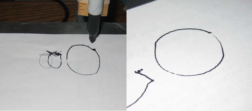
The left picture is the very first things it drew, and the right is one with a few tweaks to try to fix problems. Time to list observations:
- Alignment – My alignment simply isn’t good enough, so things are wobbling and walking and binding all over the place.
- Frame Stiffness –
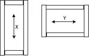
Notice how the X and Y axes butt up differently? That was part of the experiment. The Y axis design, with full-width pieces for the ends the motors mount to, is MUCH stiffer. The additional stiffness would be great for using it as an actual tool – except for the aforementioned alignment problems cause the stiffer axis to bind and walk. The X axis moves much more smoothly and freely because the motor mounting and shaft support can wobble instead of the driven part. - Couplers – The motor couplings suck in just about every way. Despite my best efforts, and the use of some suggested tricks, the holes in the shafts aren’t quite straight. Likewise, the set screws that grab the flats on the motor shafts are sliding around during direction changes, hence the elliptical shape of the first test circle. A good, misalignment-tolerant solution to this problem would alleviate most of the others, but there really isn’t room for lovejoy-type or helical couplers in there, so that will require some creative engineering. I’ve been toying with the idea of casting something out of a stiff rubbery substance, like concrete filler, but that idea is still in the half-baked phase.
- Shaft supports – The little angle-and-pipe bearing mounts screwed onto the ends of the frame suck pretty badly too. They aren’t very stiff, they aren’t very well aligned, they aren’t adjustable, and they don’t do a good job of preventing the lead screw from shifting along it’s long axis. I added a pair of jam nuts against the bearing to each one after I saw the shaft couplers shifting, and that did reduce the shifting, at the expense of even more binding and alignment problems. In a proper system, these would be thrust bearings, around a machined-down thread-less section of the leadscrew, mounted in blocks. That isn’t going to happen in a setup this cheap.
- Linear slides – The nifty nested U-channel slides are excellent … in three directions. The problem is they can walk up and down, and tend to do so in response to misalignments, hence the “jaggies” in the test circles (flex in the ruler exacerbates the problem in the trace). In principle, it should be possible to prevent upward motion with a bearing or the like pushing down on the top rail, but in practice that will be rather difficult, since there is no point on their top surface that a mounting doesn’t pass through somewhere in the range of motion. Mulling over ideas with collaborators, it seems like a different design using the rails mounted in opposed pairs each one 90° off from how they are in the current design, to make a dovetail-like structure would be superior, and not too complicated to fabricate. Perhaps in V2….
- Lead Screws – This is really a known weakness of the design – cheap UNC threaded rod just doesn’t make very good leadscrews, as standard V-threads are designed to have a fair amount of friction. The one problem I wasn’t really aware of beforehand is the cheap rolled-thread stuff doesn’t appear to be entirely straight, which doesn’t help with the alignment problems.
- Pipe frame – Using iron pipe for a frame seems like a good idea, and crops up in a lot of home-brew designs, but really doesn’t seem to work out. It’s hard to keep stiff, it’s extremely hard to mount to, and it’s nearly impossible to control angles between parts.
Plans:
It’s already giving me a taste of what accessible modern CNC toys can do, which is making me want a CNC benchtop milling machine (and lathe?)
I’m not sure how viable my mechanical parts are for actually doing any milling type operations — the frame stiffness issues can probably be worked out on the cheap, but I’m not so sure about the coupling and alignment issues. If I can work out solutions to the more egregious problems, I’m inclined to build a Z-axis of similar sophistication that can mount a rotary tool/trim router as a spindle, and teach myself basic machining on the resulting craptacular machine – It would probably be able to machine plastics, wood products, and maybe aluminum with some care and cooling, and would make a nice cheap, safe platform to learn on, albeit not one with much potential for precision. I would also consider starting from scratch and building something small and inexpensive from the lessons learned on this design, particularly with the note that certain sizes of linear motion parts are enormously cheaper than others. It likely would be more practical to buy a cheap chinese manual mill and mod it for CNC, but that wouldn’t be as educational, and it seems kind of unfortunate to get a O($1000), 100+LB hunk of fluid-and-chip spewing iron while living the uncertain life of a grad student.


Pingback: Shapeoko: Part 1 | PAPPP's Rambling
Pingback: Shapeoko: Part 5 | PAPPP's Rambling