I’ve been working on my Shapeoko in little fits and spurts that individually haven’t been terribly documentation worthy, but in aggregate are pretty interesting. Continuing from where I left off in Shapeoko: Part 5, I’ve iterated a bit on belt tensioners, switched to a commercial breakout board, put the spindle under computer control, attached the spindle to the machine, made some tentative test cuts, and added hall-effect endstop/homing switches to the X and Y axes.
Breakout
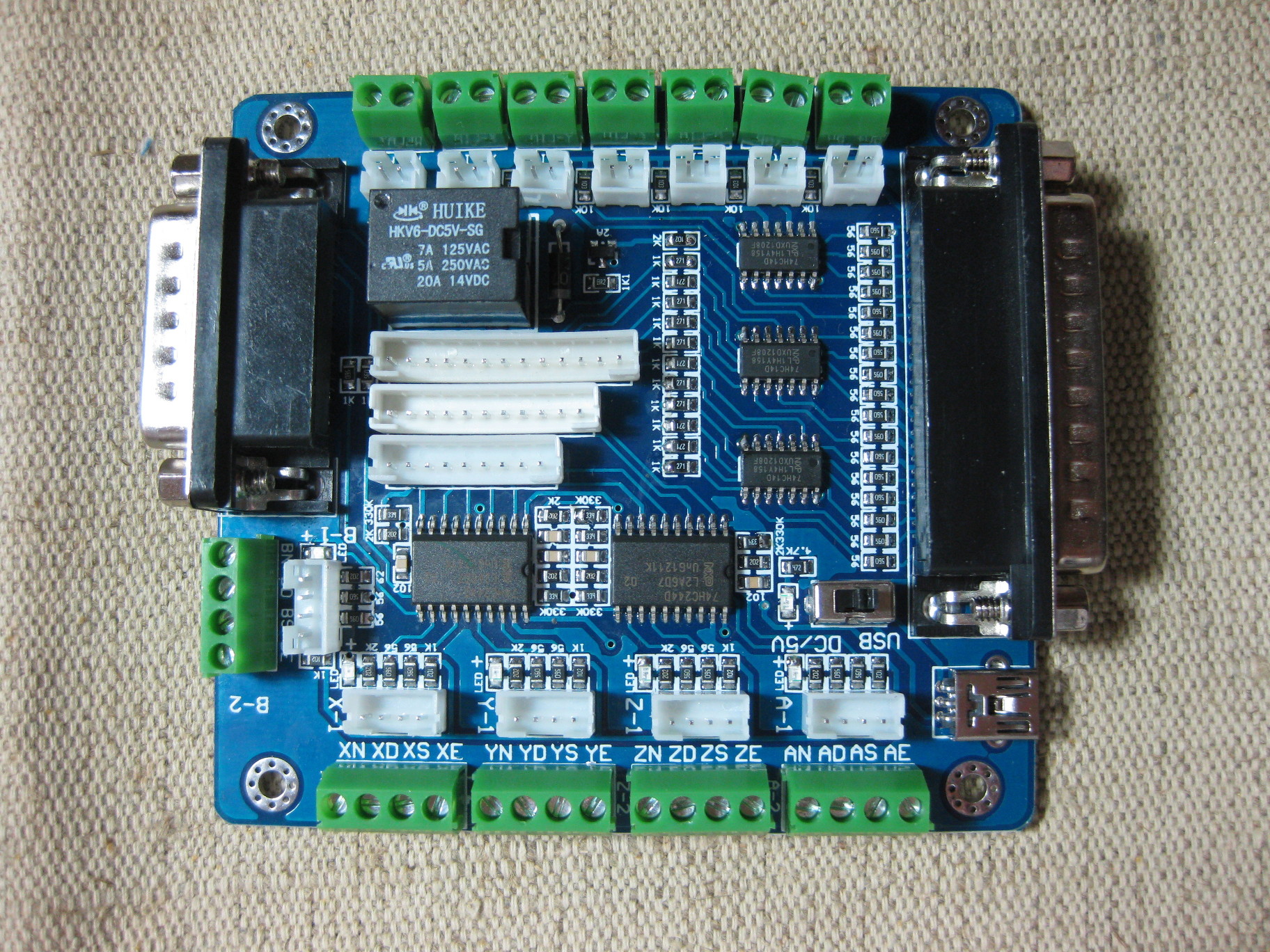
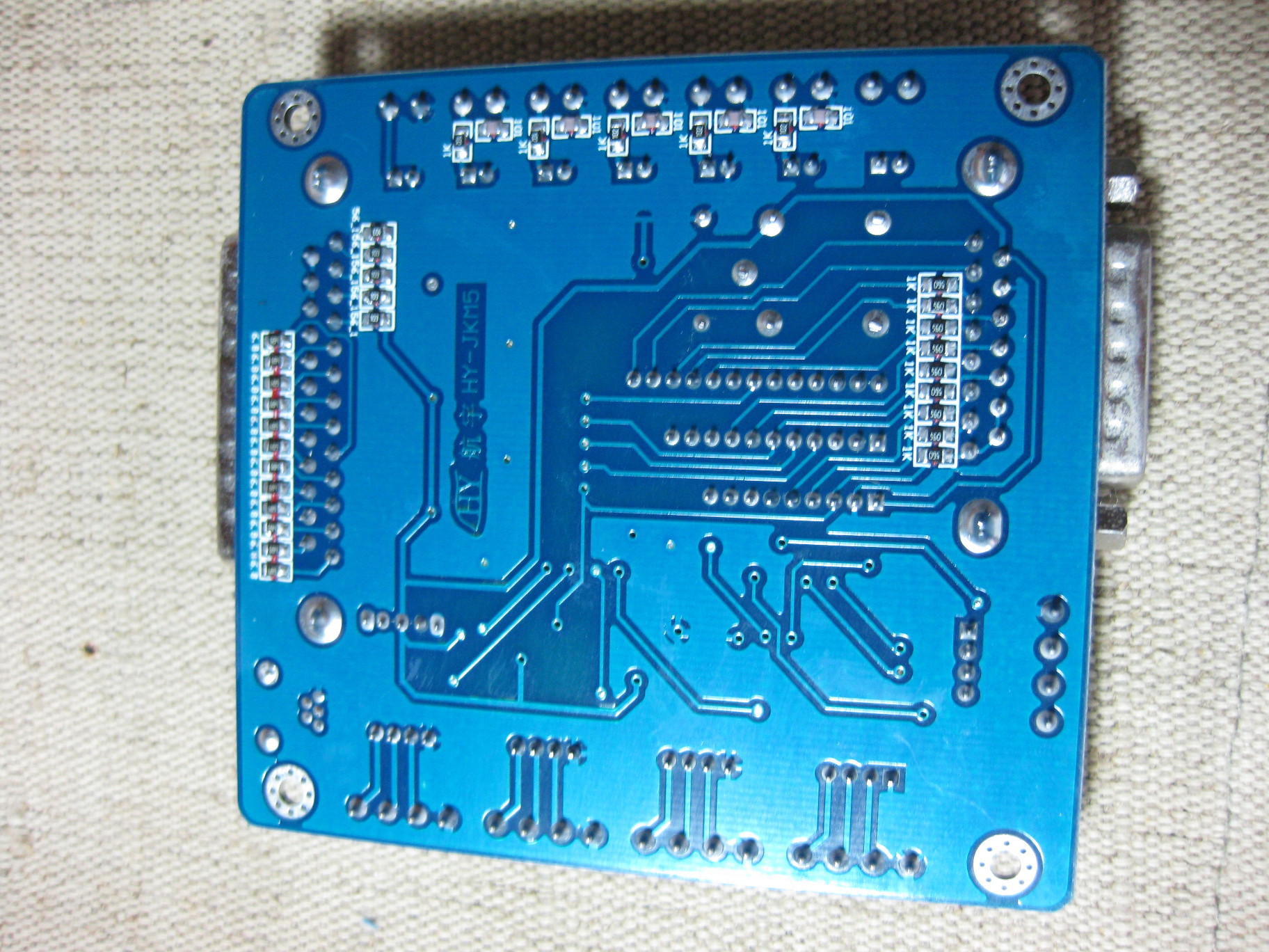
I picked up one of the many, many not terribly distinguished Chinese parallel breakout boards to get away from my sketchy breadboard and hand-soldered breakout cable solution. I selected this one from “Shenzhen Ele Technology Ltd.” on Aliexpress in particular, which is labelled HY-JKM5, comes with a mini-CD complete with bad documentation for this and a dozen other similar products, and what looked like a couple kilobucks worth of cracked CAD and CAM software for Windows. After rooting around in the documentation, and looking over this post that clarified a bit, (aside: the proprietor of that site apparently has exactly the same hobby projects I do, it makes good reading in general) I eventually figured out all the necessary correspondences. I has five axes worth of 4-pin headers (Enable,Step, and Direction on pins, plus a ground), four switch inputs, a built-in relay, and connections for an E-Stop, all broken out on to nice reliable easy-to-work-with screw terminals, as well as secondary headers for modular wiring, which I believe are XH2.54 connectors are definitely not JST XH type connectors, they need a narrower key ridge and smaller overall connector body but the documentation isn’t forthcoming, and that name may be specific to the vendor I matched image and dimensions with. I don’t think that the board is really properly isolated, but it is certainly less sketchy than what I had before.
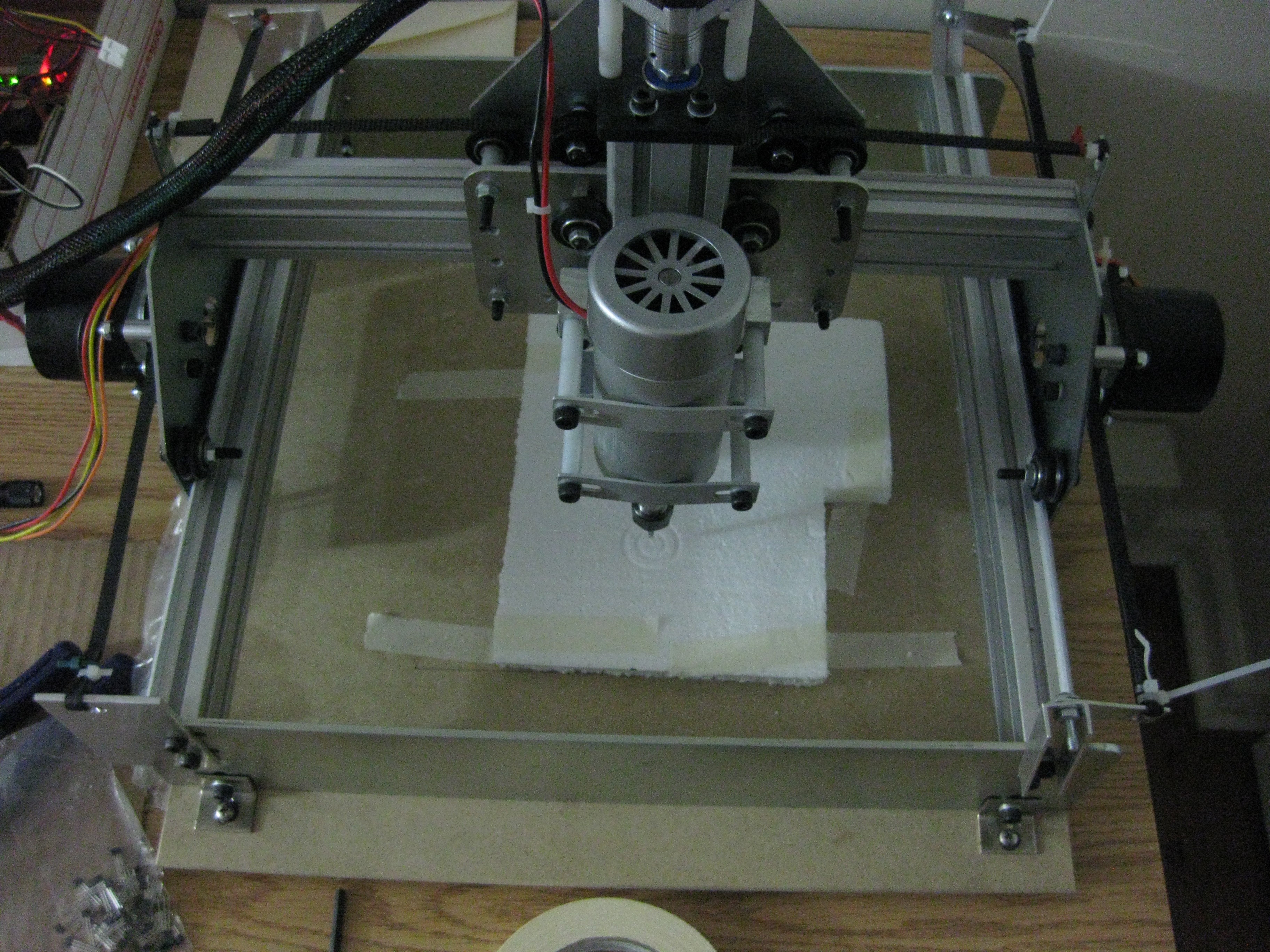
To clean up the electronics a bit, I screwed standoffs into the appropriate holes of all the pieces, and pinned them into a sheet of styrofoam in roughly the layout I intend to eventually secure them in an enclosure, to reduce tugs and confusion and mess. Ideally, I’ll have the machine cut roughly the same layout as is pressed into the Styrofoam into a piece of wood or plastic or some-such to screw down and enclose with the power supplies. That will happen around the same time I do something about random bits of hookup wire plugged into ribbon connectors and the like. I’m slowly building connectors for all the serious uglyness, but it is a very manual process to build out from header strip, harvested molex connectors and such into the harness I need.
Spindle
I talked about the spindle on it’s own in detail in my part 5: the two noteworthy things I have done are attach the spindle to the machine (using the stock Shapeoko kit brackets), and get the spindle under computer control.
Parport Pin 9 is internally connected to the relay on the breakout board, which I have interrupting the ground side of the spindle/power supply connection. Pin 17 (which would be the B axis direction as marked on the breakout) is hooked up to a scaled PWM signal fed into the input of the nearly unmarked speed controller than came with the spindle. I diddled HAL settings until I had reasonable software speed control of the spindle – my current .hal and .ini are attached to the bottom of this post.
A Cut!
Once I had the breakout and spindle working, I decided I wanted to try cutting something, just to have done it. I taped a piece of EPS foam to the bed, stuck a 1/8″ diamond-cut endmill in to the collet, homed the machine by eye, hand wrote a short piece of G-Code for some partial-depth concentric circles, let it cut. Measuring the cuts, it seems to be working properly in all axes.
Switches
Running the machine with no endstops is sketchy. Running the machine with a spindle and no endstops is really sketchy. I had a bag of generic microswitches, which I wired up with some telephone cord and tried to install, but I was never happy with the physical layout, and went looking for something else. To that end, I bought a bag of 50 A3144[-ish, they’re probably clone/counterfeit/etc.] sensors from this aliexpress seller (They have gone up at time of writing: I only paid $7.80/50). These are nice little self-contained unipolar hall effect switches – they ground their output pin when exposed to a sufficiently large magnetic field, and leave it floating otherwise. No moving parts, tiny packages, and incredibly sturdy (no, really, I’ve beaten the HELL out of some thermally, mechanically, and electrically – the only ones that died were due to a mishap with 12V reversed through the power and ground pins).

I cabled up with some normal hookup wire and electrical tape, but that caused problems with the wire being larger and stiffer than the part. While hunting for better cabling options, I saw this post espousing the wonder of servo cables for hooking up A3144, at which point I discovered that you can buy very inexpensive commercial Y-cables for servos that make perfect attachments for the max/min connections. The genders don’t work out as nicely, since the ends of the Y are male, but I’m not afraid of a little soldering.
I ended up using the jacketed ends of the Y cable as bases for a hot-glue-and-heatshrink protective shroud around each sensor, and simply hot gluing the packages to the X and Y motor plates for attachment. The trigger magnets (which are just some little rare earth discs I tacked on to an order from DealExtreme years ago) are unobtrusively attached to the ends of the rails with a bit of packing tape, and can be easily adjusted. The output and ground of each sensor is wired to the breakout board through an adapter made with some .1″ header and hookup wire, with the Vcc connections currently just pulled off to a small breadboard hooked to 5V.
Getting the switches working electrically exposed some quirks on the breakout board – for example, the pulled-up and grounded terminals of the X and Y switches are apparently in opposite order, which wouldn’t matter with a simple mechanical switch but makes the hall-effects that need a solid ground require some trial-and-error to hook up correctly. There is a little bit of hal and ini magic to get the homing behavior correct (which resulted in many impressive kerchunks as the carriages hit the end-plates), the settings in the attached files are apparently good.
One of my current puzzles is how to set up switches for Z – I think if I’m clever about it I can put a single sensor on the X carriage, a pair of magnets on the Z makerslide, and be good go to, but there are many moving obstructions in the area, and I can’t figure out where the low stop should be. Ideally, I suppose it would be easily adjustable for the installed bit length.
Etc.
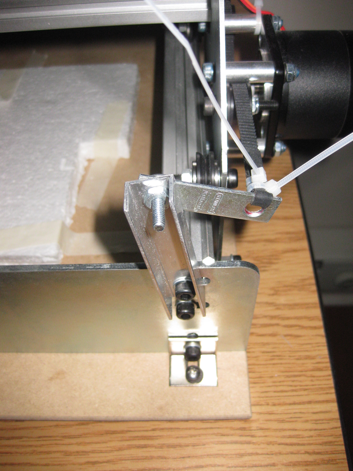
I’m not in love with either of the Y belt anchors I have right now. One side has the aluminum plates I built as a first try, which are large and hard to establish good tension with (I currently have a wood screw jammed in to the belt loop at one end to adjust the tension), and the U channel + original bracket rigs are less than finished looking. Still not sure how to do better though, maybe it will be another “the machine cuts its own improved parts” situation down the road.
My current LinuxCNC hal and ini files are attached, I had trouble finding good examples for what I wanted to happen, so hopefully these will be useful to others. These have apparently correct descriptions for homing X and Y with the A3144s, for controlling the spindle, and for general motion, although some things like the soft travel distances and Z homing are bogus or absent.
It is now, essentially, good enough to make “real things” – I just have to get it together to do so.
