Category Archives: DIY

A Staggeringly Clever Input Conditioning Circuit

Input conditioning is one of those things that snares novice designers, causes late-process changes that overrun expectations on cost and board area, and traditionally isn’t terribly well taught to EE/CPE students.

It’s on my mind because next week is the point in the semester where I drag UK’s current crop of EE/CPE sophomores through a lab exercise I designed about 5 years ago to drive home gate delays, static hazards, switch bounce, etc.

While I was thinking about it, an upperclassman who regularly digs up neat stuff sent me the cleverest input conditioning circuit I’ve ever encountered.

The circuit comes from the late, great Don Lancaster of TV Typewriter fame, who in addition to his published designs, wrote and self-published a number of instructional/reference books. He had a well-deserved reputation for clever, cheap, robust circuit designs, and this particular trick is the highest wizardry.

Here’s the whole circuit diagram from the text:

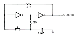
The design comes from his CMOS Cookbook (PDF, link to his own hosted copy of the 2nd ED), on p.317 amid a discussion of Flip-Flops and Clocks. It is presented as “An Alternate-Action Push Button” which is entirely correct but really undersells how clever it is, and has apparently been in there since the 1st edition in 1977.

Here’s a link to it pre-built in the CircuitJS simulator so you can manipulate it and see it work. I had to play with it for a few minutes before I really understood the genius.

The fundamental trick is that it’s a master-slave Flip-Flop where the capacitor is the master storage element, and the pair of feedback-coupled inverters is the slave. The cap tanks the next state based on the output of the first inverter when the switch is open, and induces it on the inverters on switch close. This means, in addition to latching/toggling, it de-bounces, because the capacitor sets the time constant for hysteresis. It conditions, because the load sees the output of the second inverter. No race conditions or potential oscillations, because the cap can’t charge/discharge while the switch is held. No charge is moving inside the mechanism at steady state, so it’s not leaking power. It’s brilliant.

It is only suitable for relatively slow human-scale edges, so probably not a good method for encoders or the like. You can manipulate the time constant for the de-bounce by changing the value of the capacitor, but only down to a few 10s of nF (depending on what kind of inverter you use) before it gets marginal because it doesn’t have the charge to reliably throw the input of the first inverter.

Not only is it ridiculously cheap and simple as presented, which I think intends a 4067 or 74HC04, you can built it out of anything. Any inverting CMOS gate will work. Any inverting TTL gate will work. Ridiculous old RTL or DTL inverters work. A pair of N-Channel FETs (another CircuitJS link, has an extra transistor on the output for integrity reasons) with pullups to build your own cruddy NMOS inverters works. As would P-channels with pull-downs, or BJTs with resistors for constructed RTL (though doing it that way is leaky), or various other assemblages of tiny mass produced minimum cost components to make it even more minimal (though maybe not cheaper in a modern context).

I appreciate a clever domain-crossing design, and this is the highest form.

Posted in DIY, Electronics, General | Leave a comment

Hacked Chromebook Thoughts

Several years ago I picked up a used Dell Chromebook 11 3189 (model code “Kefka”) to play with. At the time it was still receiving ChromeOS updates, had a sticky hinge that required some lubrication and manipulation to get working, and cost around $100 including the separately purchased power adapter. I’ve hacked on it in a wide variety of ways over the years, and the main interesting result is that I’m starting to think a hacked out-of-support x86 Chromebook is, in many ways, now better and cheaper than a Raspberry Pi in that role as a modern accessible extra computer to enable fearless play the Pi was intended to fill. I’ve been taking notes, so way too much detail below.

Continue reading
Posted in Computers, DIY, General, Objects | Leave a comment

A Classic 3D Printing Task: Thread Adapter

Every now and then I like to post one of these, just to show process I currently use. The magic of 3D printing is that once you’re set up this kind of quick job comes up all the time.

I have this cheap thread assortment that came on tubes rather than spools. It’s surprisingly decent thread, has good coverage for finding suitable colors for any project… and the 13mm ID tubes wobble badly on standard 4.5x40mm spool pins on sewing machines, especially when filling bobbins.

I was doing a little (ham fisted) machine sewing this weekend and it was irritating me …so I fixed it.


I’m finally getting less-incompetent with FreeCAD. Straight to “Part Design” workbench, sketch only one extruded pads’ features at a time, then decorate in any chamfers etc. at the interfaces. Import into PrusaSlicer with some sane defaults, send to the Anycubic Linear Kossel in the basement via OctoPrint (No, I don’t do it blind, I send and load the file, then go down to keep an eye on the startup sequence and make sure the filament hasn’t cracked and such), receive part.

Fit is intentionally a bit loose on all dimensions, nothing this part interacts with is consistent or close-tolerance, everything should move if it wants to, and the chamfer gets the tube seated well enough to not flop about.

FCStd and 3mf if anyone else happens to have this exact problem, which seems likely because similar thread assortments seem to be pretty ubiquitous on the usual eCommerce sites.

Posted in DIY, General, Objects | Leave a comment

Anbernic RG351(p) and Powkiddy RGB10 Max2 Button Membranes are Drop-In Compatible

I’ve had an Anbernic RG351P for roughly 2 years now, and it’s an absolutely delightful object.

For those unfamiliar: the RG351 is an example of a class of little gaming emulation handhelds that started back in the mid-to-late 2000s with things like the Dingoo A330. They are, essentially, a tiny ARM (+ usually Linux) machine the size and shape of a handheld gaming device, set up with a built-in controller specifically to run games in emulation. The stock firmware on the RG351 is an ancient EmulationStation/RetroArch/Linux stack, but there are better alternatives – IMO, throwing in a decent SD card loaded with AmberElec is the first thing to do when you get one. It will play essentially everything from the dawn of gaming through the PlayStation and some (but not all) of the Nintendo 64 library, and has limited/marginal support for PSP and DS. It is …straightforward but not the sort of thing I’ll link… to obtain the full ROMsets for these platforms, they are frankly not that large. I paid about $90 for mine, I think they’ve gone up a bit, but there are a whole range of similar options at different price points, build qualities, and platform support.

The build quality, however, isn’t perfect. It’s small-brand China-export hardware. You know you have to be a little careful with it just from handling (I keep mine in a fitted case when throwing it in a bag). I’ve been through a screen (I got red lines in my original after about a year), re-gluing the back rubber pads (original glue melted), and now after two years I wore through the membrane behind the “A” button, and that’s actually what this post is about.

I opened it up, found the worn though button, looked around online, couldn’t any in stock, contacted Anbernic through their AliExpress store front (none available), asked the subreddit (no leads), and couldn’t come up with any exact replacement membranes.

HOWEVER on inspection, the membranes from the similar Powkiddy RBG10 appeared extremely similar, and those are readily available (as a $12ish pack of all the membranes and button caps to refit an RGB10, which includes two of the 4x membranes). I ordered this set via Aliexpress, and ~16 days later when it showed up, can confirm the membranes are slightly different, but drop-in compatible.

As you can see from the photos, the Powkiddy membranes have a bit more flat area, and the bottoms of the mounting holes are filled in rather than fully punched through, but the dimensions are exactly right. The height and force of the domes is even almost identical to the originals, and at effectively $6/membrane it’s a very reasonable repair.

Posted in DIY, Electronics, Entertainment, General, Objects | Leave a comment

Most Overpriced Marchintosh


Since I recently got my HP Apollo 9000 Series 735 up and running, and it’s March, I decided to have a little Marchintosh fun and load MAE (the Macintosh Application Environment, a real officially-licensed Apple product) on to it this evening. As you can see from the photo (because I don’t have a device that can capture the video this thing outputs, and haven’t figured out screenshots under HP-UX 10.20), it works.

Continue reading
Posted in Computers, DIY, General, Objects | 1 Comment

HP Apollo 9000/735: Function Achieved

Bad light because that VESA arm mounted monitor is the only one I own that will sync to this thing

Over a year ago I started working on an inert HP Apollo 9000/735 a friend gave me from their collection to avoid moving it cross-country. I’ve recently got it working, and am posting notes about the fun.

At the end of my first post about it, I had recapped the power supply, but had not found a monitor that would talk to the enormousCRX-24z video board with its 1280×1024@72Hz Sync-on-Green via 3x BNC output, or verified the condition of the discs.
As you can see from the splash image, all of those things have been remedied.

Continue reading
Posted in Computers, DIY, General, Objects | Leave a comment

More Adventures in Tiny Stepper Motors and Drivers

A tiny stepper motor being driven by a TMC2208 Stepstick

Last summer I posted about some tiny stepper motors from the internet, thinking about them as an alternative to mechatronic standbys like those terrible SG90 type servos or larger and differently terrible 28BYJ-48 geared steppers driven through a ULN2003.

At the time, I tried one with an A4988 stepstick from the top of my parts bin, and it didn’t work, so I figured there was some limitation and stuck to directly driving with H-bridges.
…it turns out the “limitation” was that the cheap current-setting potentiometer on that particular stepstick was broken so it was driving no output current.

Discoveries:

  • Those little bipolar stepper motors work fine with bipolar stepper drivers.
  • Generational gains in bipolar stepper driver ICs are substantial (eg. A4988 -> TMC2208).
  • The venerable 28BYJ-48 unipolar stepper motor is easily modified to run from bipolar drivers.
Continue reading
Posted in DIY, Electronics, General, Objects | Leave a comment

Installing SKS B53 Fenders on a Giant Escape Disc

Giant Escape 3 Disc with SKS B53 Fenders
Giant Escape 3 Disc with SKS B53 fenders, modified to fit

I’ve been biking a fair amount lately after a 20-odd year hiatus; I decided last year that I wanted to start biking, bought a Giant Escape 3 Disc near the end of summer, but didn’t get confident enough riding to use it around campus last year among the students texting their way to their first (next?) vehicular manslaughter charge before they flocked back.

This summer, I’ve been dong my commute into campus on it, plus a significant amount of fun/exercise riding, and the top fixable annoyance has become getting sprayed at the slightest hint of wet. I did some hackin’ that I haven’t seen on the interwebs to fit the fenders I picked to the frame, which is the point of this post.

Continue reading
Posted in DIY, General, Objects | Leave a comment

Onn Surf 8 (100003561) Hacking

I have an Onn Surf 8 (One of the surprisingly-not-that-shitty ultra-cheap Walmart tablets) that my research group bought a couple of to use as Android dev testbeds. I’ve been occasionally using it as a normal tablet since I have it around, and have been consistently irritated by the collection of bloatware it comes with…. so I decided to hack it. To tl;dr this whole thing, ignore the collection of typically scammy Android dev forum and blogspam crud, and use the open-source mtkclient for your MediaTek Android device hackin’ needs.

Continue reading
Posted in Computers, DIY, Electronics, General, Objects | Leave a comment

Tiny Stepper Motors

I impulse bought a 5 pack of tiny stepper motors off Amazon for $3 to satisfy my curiosity. A colleague showed them to me and asked if I knew anything about them and …I didn’t, but they were too cheap and interesting not to try.

I couldn’t find any documentation on the internet from the identifying marks, so I burnt an afternoon figuring them out, and I’m posing my notes in case anyone else wants to make use of them.

Amazon product is “5 Pcs 2 Phase 4 Wire Micro Stepper Motor with Cable 3-5v Dc Dia 8mm Mini Stepper Motor Micro Stepping Motor for Digital Products Camera”. They look like they’re drop-in replacements or surplus from the production of …something… but I don’t see any obvious leads as to what.

The labeling on the motor itself is “SRG0808 003PLK5” which doesn’t turn up anything useful in a quick search, and the bag they came in is labeled “Fashion Worlds stepper motor 9496 x5” which is also not something googlable.

The motor comes attached to a flat flex cable with various adhesive pads built in, a boardlet, and a connector at one end. The output shaft is set in a brass gear roughly 2.75mm diameter with 12 involute profile teeth, about 3mm long – I don’t know small gears well enough to infer a ton from this, but it does seem like there is a lot of compatible gearing on the market.

Test setup for one of these steppers

To get around the lack of documentation, I probed one out with a DMM then built a test rig out of a dual L9110S H-Bridge board and a little STM32F103 dev board with the AccelStepper Arduino library to figure out the details.

They appear to be 20 steps per revolution motors, though they seem to work noticeably better with a half-step drive pattern.
They work nicely at 3.3V, but get a little hotter than I’m comfortable with if energized for an extended period of time; I also tried 5V and it seems to tolerate that fine as well, gain a noticeable amount of extra torque, and get appreciably louder.

I don’t have the tools around to easily test the effective torque, but was way more than I expected based on my experiences with other small hobby motors. In my little taped-to-the-table test setup (pictured), if I jammed a fingernail into the rotor when it was already at speed at around at about 1000 steps/s on a 5V supply, the motor and/or nail deflected rather than missing steps.

Motor Diagram

If you look at the motor with the output shaft facing away from you and label the four pads A,B,C,D, the phases are A-D and B-C with about 9Ω across each phase.

FPC Connector Pinout

If you look at the attached flat flex cable with the end pointed toward you, it has 7 contacts. For reference, let’s refer to them numbered 1-7 left to right. The ribbon itself is 4mm wide, and the contacts appear to be 0.5mm pitch, so it would probably mate with any of the various “7Pin 0.5mm Pitch FFC FPC” connectors floating around on the market for cheap if you wanted to spin a driver board for it that used the included cable.

The last 4 cable pins correspond to the motor terminals 4-D, 5-C, 6-B, 7-A… but for experimentation it’s easier to just solder leads directly to the motor pads. I used two pairs out of some old stranded CAT5, visible in the top picture.

IR Reflective Object Sensor Breakout


There is a bonus component on a little arc-shaped boardlet built into the flat flex. It appears to be some manner of reflective infrared optical sensor, which I assume was used to establish a home position in whatever these were designed for use in – frankly since it has convenient mounting holes and wiring it would be pretty nice to use the same way in most applications I would want one of these in.

The first three ribbon pins are attached to this part, and none of these pins are shared with the motor itself. For discussion, let’s number the pins 1,2 left to right on the side toward the flex cable, and 3,4 right to left along the other in typical IC fashion. The pins are broken out Part 1 = Flex 1, Part 2 = Flex 2, Part 3 = also Flex 1, Part 4 = Flex 3.

Two of the pins (+ on 2, – on 3) appear to be a diode with a 1V forward voltage, and after I thought about it and checked with a camera with a bad IR filter, it is an infrared LED. The other pair seem to be a phototransistor or similar; it reads about 1.5MΩ from pin 4 to pin 1 in darkness and 1KΩ across the same with an IR LED pointed at it.

I’m not sure what I’m going to do with these, but they seem promising for small motion systems, especially since (if I bought bulk packs of each from China) you could get the motor and pair of H-bridges to drive it for under a dollar. Hopefully I’ll run into something to play with them in and/or my reversing work will enable someone else’s cool project.

Posted in DIY, Electronics, General | 2 Comments